Manual switch configuration
This section describes the configuration of the MX5108n switches. Each PowerEdge MX7000 chassis has two MX5108n switches in the A
fabric (A1 and A2). Each of the two switches gets the same configuration except for the IP address and the VLT Backup Destination IP
Address. The IP address of each switch module is assigned using the chassis management interface (MSM).
Topics:
•
•
VLANs and subnets for manual switch configuration
•
•
•
•
Configure the uplink Link Aggregation Control Protocol
•
Configure the server facing ports
•
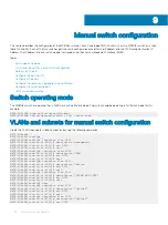
Switch operating mode
The MX5108n switches operate either in Full Switch or SmartFabric mode. The switch should be operating in Full Switch mode for this
example.
MX7K-IOM-A2# show switch-operating-mode
MX7K-IOM-A2# Switch-Operating-Mode : Full Switch Mode
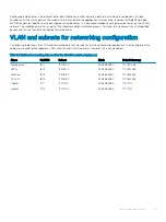
VLANs and subnets for manual switch configuration
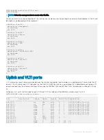
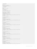
Create the VLANs required for Cloud Foundation by using the following commands:
MX7K-IOM-A2#
MX7K-IOM-A2(config)#
MX7K-IOM-A2(config)# interface vlan 1611
MX7K-IOM-A2(conf-if-vl-1611)# description Management
MX7K-IOM-A2(conf-if-vl-1611)# mtu 9216
MX7K-IOM-A2(conf-if-vl-1611)# exit
MX7K-IOM-A2(config)# interface vlan 1612
MX7K-IOM-A2(conf-if-vl-1612)# description VSAN
MX7K-IOM-A2(conf-if-vl-1612)# mtu 9216
MX7K-IOM-A2(conf-if-vl-1612)# exit
MX7K-IOM-A2(config)# interface vlan 1613
MX7K-IOM-A2(conf-if-vl-1613)# description VMotion
MX7K-IOM-A2(conf-if-vl-1613)# mtu 9216
MX7K-IOM-A2(conf-if-vl-1613)# exit
MX7K-IOM-A2(config)# interface vlan 1614
MX7K-IOM-A2(conf-if-vl-1614)# description "VXLAN NSX VTEP"
MX7K-IOM-A2(conf-if-vl-1614)# mtu 9216
MX7K-IOM-A2(conf-if-vl-1614)# exit
MX7K-IOM-A2(config)# exit
MX7K-IOM-A2(config)# interface vlan 2711
MX7K-IOM-A2(conf-if-vl-2711)# description "Uplink1"
MX7K-IOM-A2(conf-if-vl-2711)# mtu 9216
MX7K-IOM-A2(conf-if-vl-2711)# exit
MX7K-IOM-A2(config)# interface vlan 2712
MX7K-IOM-A2(conf-if-vl-2712)# description "Uplink2"
MX7K-IOM-A2(conf-if-vl-2712)# mtu 9216
9
46
Manual switch configuration
Summary of Contents for PowerEdge MX7000
Page 1: ...Dell EMC VMware Cloud Foundation for PowerEdge MX7000 Deployment Guide ...
Page 8: ...Figure 1 Cloud Foundation deployment workflow 8 Overview ...
Page 27: ...Figure 19 Dual PowerEdge MX7000 enclosure configuration Physical layout 27 ...
Page 29: ...Figure 20 MX9002m Management module cabling Physical layout 29 ...
Page 30: ...Figure 21 Connectivity between FSE modules and FEM modules 30 Physical layout ...
Page 31: ...Figure 22 Uplinks to customer network environment Physical layout 31 ...
Page 42: ...Figure 25 MX9002m Management Module cabling 42 Networking requirements ...
Page 43: ...Figure 26 Connectivity between FSE modules and FEM modules Networking requirements 43 ...
Page 44: ...Figure 27 Uplinks to customer network environment 44 Networking requirements ...


