background image

Dell EMC PowerEdge R840

Technical Specifications

Regulatory Model: E49S Series
Regulatory Type: E49S001

Summary of Contents for PowerEdge R840

Page 1: ...Dell EMC PowerEdge R840 Technical Specifications Regulatory Model E49S Series Regulatory Type E49S001 ...

Page 2: ...amage to hardware or loss of data and tells you how to avoid the problem WARNING A WARNING indicates a potential for property damage personal injury or death 2018 Dell Inc or its subsidiaries All rights reserved Dell EMC and other trademarks are trademarks of Dell Inc or its subsidiaries Other trademarks may be trademarks of their respective owners 2018 10 Rev A01 ...

Page 3: ...cifications 20 Expansion card riser specifications 20 Memory specifications 21 RAID controller specifications 22 Drive specifications 22 Drives 22 Optical drives 22 Tape drives 23 Ports and connectors specifications 23 USB ports 23 NIC ports 23 VGA ports 24 Serial connector 24 IDSDM or vFlash module 24 Video specifications 24 Environmental specifications 25 Standard operating temperature 26 Expand...

Page 4: ...dded System Diagnostics 40 4 Documentation resources 41 5 Getting help 43 Contacting Dell 43 Documentation feedback 43 Accessing system information by using QRL 43 Quick Resource Locator for PowerEdge R840 system 44 Receiving automated support with SupportAssist 44 Recycling or End of Life service information 44 4 Contents ...

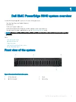
Page 5: ...out supported drives see the Technical specifications section NOTE All instances of SAS SATA hard drives NVMe and SSDs are referred to as drives in this document unless specified otherwise Topics Front view of the system Rear view of the system Inside the system Locating the Service Tag of your system System Information Label Front view of the system Figure 1 Front view 24 x 2 5 inch drive system ...

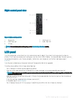
Page 6: ... control panel view with optional iDRAC Quick Sync 2 0 indicator 1 Status LED indicators 2 System health and system ID indicator 3 iDRAC Quick Sync 2 wireless indicator optional NOTE iDRAC Quick Sync 2 feature allows you to manage your system using mobile devices This feature is only available on certain configurations For more information about the feature see the Integrated Dell Remote Access Co...

Page 7: ...tional front bezel The optional front bezel is hot pluggable The statuses and conditions of the LCD panel are outlined here The LCD backlight is white during normal operating conditions When the system needs attention the LCD backlight turns amber and displays an error code followed by descriptive text NOTE If the system is connected to a power source and an error is detected the LCD turns amber r...

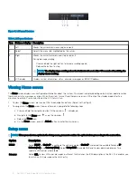
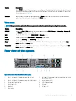
Page 8: ...de after five minutes of inactivity Press any button on the LCD to turn it on 1 To view the Home screen press one of the three navigation buttons Select Left or Right 2 To navigate to the Home screen from another menu complete the following steps a Press and hold the navigation button till the up arrow is displayed b Navigate to the Home icon using the up arrow c Select the Home icon d On the Home...

Page 9: ...ys the MAC addresses for iDRAC iSCSI or Network devices Name Displays the name of the Host Model or User String for the system Number Displays the Asset tag or the Service tag for the system Power Displays the power output of the system in BTU hr or Watts The display format can be configured in the Set home submenu of the Setup menu Temperature Displays the temperature of the system in Celsius or ...

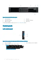
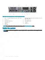
Page 10: ...r supply units 2 5 System identification button 6 iDRAC9 dedicated port 7 USB 3 0 ports 2 8 VGA port 9 Serial port 10 NIC ports 4 11 Rear handle NOTE For more information about the ports and connectors see the Technical Specifications section Inside the system NOTE Components that are hot swappable have orange touch points and the components that are not hot swappable have blue touch points 10 Del...

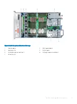
Page 11: ...ithout rear drive cage 1 Drive backplane 2 SAS Expander board 3 Cooling fans 6 4 System board 5 Full height expansion card Riser 2 6 Full height expansion card Riser 1 7 Intrusion switch Dell EMC PowerEdge R840 system overview 11 ...

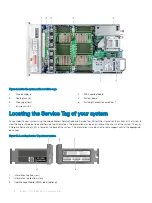
Page 12: ...ull out the information tag in front of the system to view the Express Service Code and Service Tag Alternatively the information may be on a sticker on the chassis of the system The mini Enterprise Service Tag EST is found on the back of the system This information is used by Dell to route support calls to the appropriate personnel Figure 10 Locating Service Tag of your system 1 Information tag t...

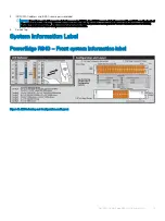
Page 13: ...ack of the system Information tag This section of label will be blank if you have not opted for secure default access to iDRAC then the default user name and password are root and calvin 5 Service Tag System Information Label PowerEdge R840 Front system information label Figure 11 LED behavior and Configuration and Layout Dell EMC PowerEdge R840 system overview 13 ...

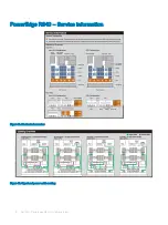
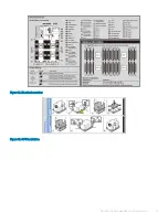
Page 14: ...PowerEdge R840 Service information Figure 12 Mechanical overview Figure 13 Signal and power cable routing 14 Dell EMC PowerEdge R840 system overview ...

Page 15: ...Figure 14 Electrical overview Figure 15 CPU installation Dell EMC PowerEdge R840 system overview 15 ...

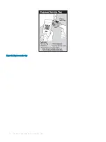
Page 16: ...Figure 16 Express service tag 16 Dell EMC PowerEdge R840 system overview ...

Page 17: ... Chassis weight Processor specifications Supported operating systems PSU specifications System battery specifications Expansion card riser specifications Memory specifications RAID controller specifications Drive specifications Ports and connectors specifications Video specifications Environmental specifications 2 Technical specifications 17 ...

Page 18: ...ll handle 482 mm 18 97 inches 434 mm 17 08 inches 444 0 17 48 inches 86 8 mm 3 41 inches 37 84 mm 1 41 inches 23 9 mm 0 94 inches 812 mm 31 96 inches 842 mm 33 14 inches 902 mm 35 51 inches Zb refers to the nominal rear wall external surface where the system board I O connectors are located Chassis weight Table 3 Chassis weight System Maximum weight with all drives SSDs 2 5 inch 36 6 kg 80 68 lb 1...

Page 19: ...tion maximum Frequency Voltage High line 200V 240 V Low line 100 V 140 V DC Current 750 W AC Platinum 2891 BTU hr 50 60 Hz 100 240 V AC autoranging 750 W 750 W NA 10 A 5 A 750 W AC Titanium 2843 BTU hr 50 60 Hz 200 240 V AC autoranging 750 W NA NA 5 A 750 W Mixed Mode HVDC for China only Platinum 2891 BTU hr 50 60 Hz 100 240 V AC autoranging 750 W 750 W NA NA N A 2891 BTU hr N A 240 V DC autorangi...

Page 20: ...ing NOTE This system is also designed to connect to the IT power systems with a phase to phase voltage not exceeding 240 V NOTE PSUs rated for 1100 W AC or 1100 W Mixed Mode HVDC and higher require high line voltage 200 240 V AC to supply their rated capacity System battery specifications The PowerEdge R840 system supports CR 2032 3 0 V lithium coin cell system battery Expansion card riser specifi...

Page 21: ...ser 2 Processor 2 Full height Full length x16 X8 PCIe Riser 2 Processor 2 Full height Half length x8 Memory specifications The PowerEdge R840 system supports up to 48 288 pins RDIMMs LRDIMMs and NVDIMM Ns supported with speeds of 2667 MT s 2400 MT s 2133 MT s and 1866 MT s with support for memory optimized operation Table 6 Memory specifications DIMM type DIMM rank DIMM capacity Dual processors Qu...

Page 22: ...rive specifications Drives The PowerEdge R840 system supports SAS SATA Nearline SAS hard drives SSDs or NVMe drives Table 8 Supported drive options for PowerEdge R840 system Chassis options Configurations Eight hard drive chassis Up to eight 2 5 inch SAS SATA front accessible drives in slots 0 7 Up to eight 2 5 inch SATA front accessible drives in slots 0 7 Twenty four drive chassis Up to twenty f...

Page 23: ... Gb FC tape drives Ports and connectors specifications USB ports The PowerEdge R840 system supports both USB 2 0 compliant ports and USB 3 0 compliant ports The following table provides more information about the USB specifications Table 9 USB specifications Front panel Back panel Internal USB Two USB 2 0 compliant ports One micro USB 2 0 compliant port for iDRAC Direct NOTE The micro USB 2 0 comp...

Page 24: ...SD module IDSDM or vFlash module In 14th generation of PowerEdge servers IDSDM or vFlash module is combined into a single card module and are available in these configurations vFlash or vFlash and IDSDM The IDSDM or vFlash module is located in a slot on the back of the system The module supports three microSD cards two cards for IDSDM and one card for vFlash The following capacities are supported ...

Page 25: ...0 F 149 F Continuous operation for altitude less than 950 m or 3117 ft 10 35 C 50 F 95 F with no direct sunlight on the equipment Fresh air For information about fresh air see the Expanded Operating Temperature section Maximum temperature gradient operating and storage 20 C h 36 F h Table 12 Relative humidity specifications Relative humidity Specifications Storage 5 to 95 RH with 33 C 91 F maximum...

Page 26: ... 547 ft above 950 m 3 117 ft 35 40 C 95 104 F Maximum temperature is reduced by 1 C 175 m 1 F 319 ft above 950 m 3 117 ft 40 45 C 104 F 113 F Maximum temperature is reduced by 1 C 125 m 1 F 228 ft above 950 m 3 117 ft Standard operating temperature Table 17 Standard operating temperature specifications Standard operating temperature Specifications Continuous operation for altitude less than 950 m ...

Page 27: ...temperature is specified for a maximum altitude of 950 m for Fresh Air Cooling Do not perform cold start below 5 C due to hard drive constraints Apache Pass DIMM NVDIMM PCIe SSD and NVMe are not supported Tape Backup Unit TBU is not supported in Fresh Air LRDIMM 32 GB is not supported in x4 sockets configuration Rear installed drives and GPU configuration are not supported Redundant power supplies...

Page 28: ...t support Intel Xeon Platinum 8176 165 W 28 C35 C30 C30 C35 Intel Xeon Platinum 8170 165 W 26 C35 C30 C30 C35 Intel Xeon Gold 6150 165 W 18 C35 C30 C30 C35 Intel Xeon Gold 6134 130 W 8 C35 C30 C30 C35 Intel Xeon Gold 6128 115 W 6 C35 C30 C30 C35 Intel Xeon Gold 5122 105 W 4 C35 C30 C30 C35 Intel Xeon Platinum 8156 105 W 4 C35 C30 C30 C35 Intel Xeon Platinum 8164 150 W 26 C35 C30 C30 C35 Intel Xeon...

Page 29: ...C30 C30 C35 Intel Xeon Gold 5115 85 W 10 C35 C30 C30 C35 Table 20 Configuration based ambient temperature restrictions R840 configurations Backplane 8 x 2 5 inch SAS SATA 24 x 2 5 inch SAS SATA Expander 2x 2 5 inch rear 24 x 2 5 inch NVMe Expander 24 x 2 5 inch SAS SATA NVMe Expander R840 configurations No Of processors supported 4 4 4 2 Processor heat sink 1U 1U 1U 1U No Of GPUs supported Non GPU...

Page 30: ...5 C35 Intel Xeon Gold 6128 115 W 8 C35 C35 C35 C35 Intel Xeon Gold 5122 105 W 6 C35 C35 C35 C35 Intel Xeon Platinum 8156 105 W 4 C35 C35 C35 C35 Intel Xeon Platinum 8164 150 W 4 C35 C35 C35 C35 Intel Xeon Platinum 8160 150 W 26 C35 C35 C35 C35 Intel Xeon Gold 6148 150 W 24 C35 C35 C35 C35 Intel Xeon Gold 6142 150 W 20 C35 C35 C35 C35 Intel Xeon Gold 6136 150W 16 C35 C35 C35 C35 Intel Xeon Platinum...

Page 31: ...ronmental conditions Remediation of environmental conditions is the responsibility of the customer Table 21 Particulate contamination specifications Particulate contamination Specifications Air Filtration Data center air filtration as defined by ISO Class 8 per ISO 14644 1 with a 95 upper confidence limit NOTE This condition applies to data center environments only Air filtration requirements do n...

Page 32: ...ion Specifications Copper Coupon Corrosion 300 Å month per Class G1 as defined by ANSI ISA71 04 1985 Silver Coupon Corrosion 200 Å month as defined by AHSRAE TC9 9 NOTE Maximum corrosive contaminant levels measured at 50 relative humidity 32 Technical specifications ...

Page 33: ...onfiguration utility program Temperature indicator The indicator turns solid amber if the system experiences a thermal error for example the ambient temperature is out of range or there is a fan failure Ensure that none of the following conditions exist A cooling fan has been removed or has failed System cover air shroud memory module blank or back filler bracket is removed Ambient temperature is ...

Page 34: ...thy and system ID mode is not active Press the system health and system ID button to switch to system ID mode Blinking blue Indicates that the system ID mode is active Press the system health and system ID button to switch to system health mode Solid amber Indicates that the system is in fail safe mode If the problem persists see the Getting help section Blinking amber Indicates that the system is...

Page 35: ... If the problem persists see the Getting help section For more information see Integrated Dell Remote Access Controller User s Guide at Dell com idracmanuals or Dell OpenManage Server Administrator User s Guide atDell com openmanagemanuals Solid amber Indicates that the system is in fail safe mode Restart the system If the problem persists see the Getting help section Blinking amber Indicates that...

Page 36: ...ator is green and activity indicator is off The NIC is connected to a valid network at its maximum port speed and data is not being sent or received Link indicator is amber and activity indicator is off The NIC is connected to a valid network at less than its maximum port speed and data is not being sent or received Link indicator is blinking green and activity is off NIC identify is enabled throu...

Page 37: ...o PSUs are installed both the PSUs must have the same type of label for example Extended Power Performance EPP label Mixing PSUs from previous generations of PowerEdge servers is not supported even if the PSUs have the same power rating This results in a PSU mismatch condition or failure to turn on the system CAUTION When correcting a PSU mismatch replace only the PSU with the blinking indicator S...

Page 38: ...ed voltage CAUTION If two PSUs are installed both the PSUs must have the same type of label for example Extended Power Performance EPP label Mixing PSUs from previous generations of PowerEdge servers is not supported even if the PSUs have the same power rating This results in a PSU mismatch condition or failure to turn on the system CAUTION When correcting a PSU mismatch replace only the PSU with ...

Page 39: ...Advanced Host Controller Interface AHCI mode the status LED indicator does not turn on Table 30 Drive indicator codes Drive status indicator code Condition Flashes green twice per second Identifying drive or preparing for removal Off Drive ready for removal NOTE The drive status indicator remains off until all drives are initialized after the system is turned on Drives are not ready for removal du...

Page 40: ...rom Boot Manager Run the Embedded System Diagnostics ePSA if your system does not boot 1 When the system is booting press F11 2 Use the up arrow and down arrow keys to select System Utilities Launch Diagnostics 3 Alternatively when the system is booting press F10 select Hardware Diagnostics Run Hardware Diagnostics The ePSA Pre boot System Assessment window is displayed listing all devices detecte...

Page 41: ...the Getting Started Guide document that is shipped with your system Dell com poweredgemanuals Configuring your system For information about the iDRAC features configuring and logging in to iDRAC and managing your system remotely see the Integrated Dell Remote Access Controller User s Guide For information about understanding Remote Access Controller Admin RACADM subcommands and supported RACADM in...

Page 42: ...ng Dell SupportAssist see the Dell EMC SupportAssist Enterprise User s Guide Dell com serviceabilitytools For information about partner programs enterprise systems management see the OpenManage Connections Enterprise Systems Management documents Dell com openmanagemanuals Working with the Dell PowerEdge RAID controllers For information about understanding the features of the Dell PowerEdge RAID co...

Page 43: ...pport page that lists the various support categories is displayed 4 For general support a Select your product category b Select your product segment c Select your product The support page that lists the various support categories is displayed 5 For contact details of Dell Global Technical Support a Click Global Technical Support b The Contact Technical Support page is displayed with details to cal...

Page 44: ... SupportAssist monitors your Dell EMC devices and automatically detects hardware issues both proactively and predictively Automated case creation When an issue is detected SupportAssist automatically opens a support case with Dell EMC Technical Support Automated diagnostic collection SupportAssist automatically collects system state information from your devices and uploads it securely to Dell EMC...

Reviews: