
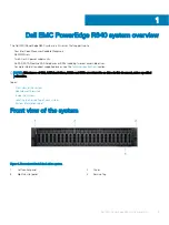
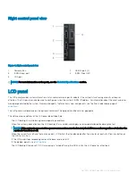
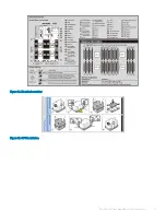

Right control panel view
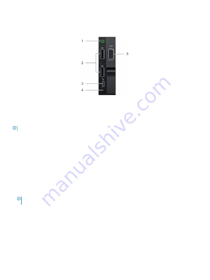
Figure 4. Right control panel view
1
Power button
2
USB 2.0 port (2)
3
iDRAC Direct port
4
iDRAC Direct LED
5
VGA port
NOTE:
For more information on the ports, see the
section.
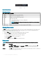
LCD panel
The LCD panel provides system information, status, and error messages to indicate if the system is functioning correctly or requires
attention. The LCD panel can also be used to configure or view the system’s iDRAC IP address. For information about the event and error
messages generated by the system firmware and agents that monitor system components, see the Error Code Lookup page, at
The LCD panel is available only on the optional front bezel. The optional front bezel is hot pluggable.
The statuses and conditions of the LCD panel are outlined here:
•
The LCD backlight is white during normal operating conditions.
•
When the system needs attention, the LCD backlight turns amber, and displays an error code followed by descriptive text.
NOTE:
If the system is connected to a power source and an error is detected, the LCD turns amber regardless of whether the
system is turned on or off.
•
When the system turns off and there are no errors, LCD enters the standby mode after five minutes of inactivity. Press any button on
the LCD to turn it on.
•
If the LCD panel stops responding, remove the bezel and reinstall it.
If the problem persists, see
•
The LCD backlight remains off if LCD messaging is turned off using the iDRAC utility, the LCD panel, or other tools.
Dell EMC PowerEdge R840 system overview
7


