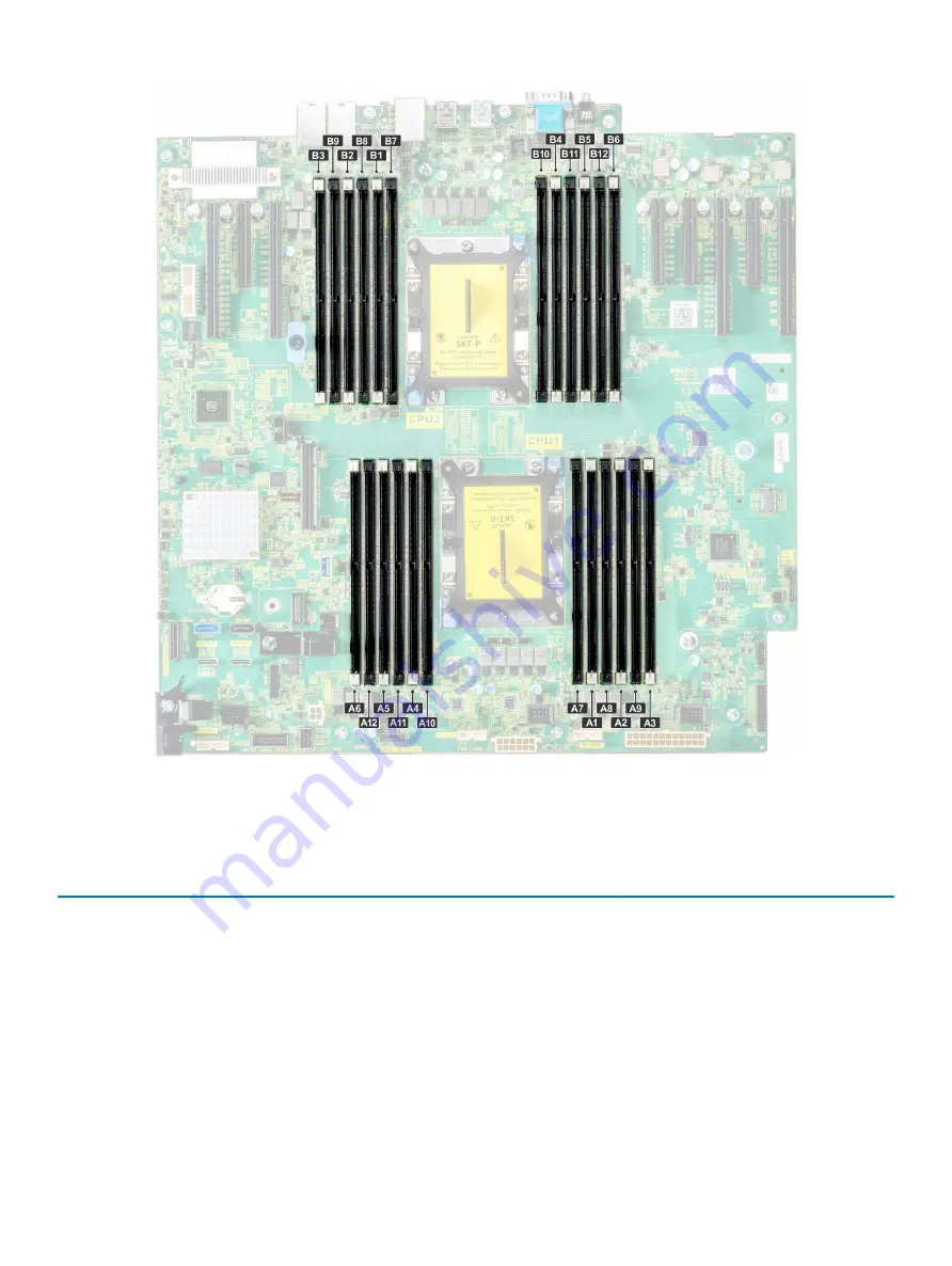
Figure 63. System memory view
Table 34. Memory channels
Proces
sor
Channel 0
Channel 1
Channel 2
Channel 3
Channel 4
Channel 5
Proces
sor 1
Slots A1 and A7
Slots A2 and A8
Slots A3 and A9
Slots A4 and A10
Slots A5 and A11
Slots A6 and A12
Proces
sor 2
Slots B1 and B7
Slots B2 and B8
Slots B3 and B9
Slots B4 and B10
Slots B5 and B11
Slots B6 and B12
The following table shows the memory populations and operating frequencies for the supported configurations:
110
Installing and removing system components
Summary of Contents for PowerEdge T640
Page 23: ...Figure 16 Configuration and layout Dell EMC PowerEdge T640 overview 23 ...
Page 24: ...Figure 17 Electrical overview 24 Dell EMC PowerEdge T640 overview ...
Page 25: ...Figure 18 Memory information Dell EMC PowerEdge T640 overview 25 ...


