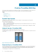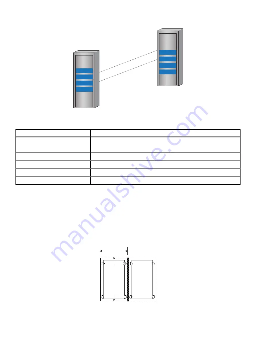
System
bay 1
Engine 8
Engine 3
Engine 4
Engine 7
System
bay 2
Engine 1
Engine 2
Engine 6
Engine 5
Figure 8. Dispersed layout, PowerMax 8000
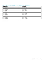
Table 19. Fabric dispersion kits for System Bay 2
Kit Part Number
Description
106-887-147
VMAX EVEREST DISPERSION TRANSCEIVER KIT
(1 kit per engine required)
106-887-034
Engine 5 Dispersion Kit 30m (Green)
106-887-035
Engine 6 Dispersion Kit 30m (Blue)
106-887-036
Engine 7 Dispersion Kit 30m (Red)
106-887-037
Engine 8 Dispersion Kit 30m (White)
Dimensions for array layouts
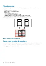
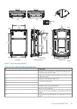
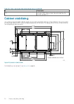
Placing arrays in the data center or computer room involves understanding dimensions, planning for cutouts, and ensuring clearance for
power and host cables.
•
On nonraised floors, cables are routed overhead. An overhead routing bracket is provided to allow easier access of overhead cables
into the bay
•
On raised floors, cables are routed across the subfloor beneath the tiles.
•
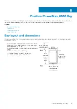
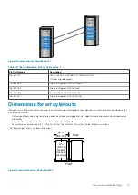
Ensure there is a service area of 42 in (106 cm) for the front and 30 in (76 cm) for the rear of each system bay.
The following figure shows the layout dimensions:
Front
Rear
47 in.
(119 cm)
Includes
front and
rear doors
24.02 in.
(61.01 cm)
24 in.
(61 cm)
Figure 9. Layout dimensions, PowerMax 8000
Position PowerMax 8000 Bay
31


