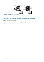
This procedure requires the Dell EMC Customer Engineer to verify that the customer's electrician has complied with power specifications.
Once verified, the Dell EMC Customer Engineer makes the required power connections overhead or under the floor.
NOTE:
Utilize proper strain relief methods when customer-provided power drops are located overhead or wall-mounted.
Steps
1. Have the customer verify that their electrician has complied with power specifications for voltage levels and redundancy. If the
customer cannot verify this, provide them with a copy of Procedure A. Inform the customer that their array may prematurely shut
down in the event of a site power issue.
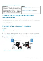
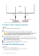
2. Access the labeled, power cables (beneath raised floor or overhead) to verify that the customer-supplied power cables are properly
labeled as shown in
Figure 29. Circuit breakers OFF — No AC power
on page 64 and described in Procedure A, Task 2.
3. Compare the numbers on the customer-supplied power cables for each storage bay to verify that power zone A and power zone B are
powered by a different customer-supplied PDU.
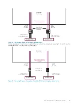
4. Connect the customer's PDU AC cables to the storage bay power zones as described in Procedure A, Task 2.
5. Record the customer-supplied PDU information as described in Procedure A, Task 2.
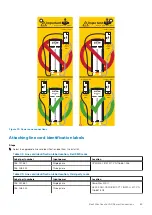
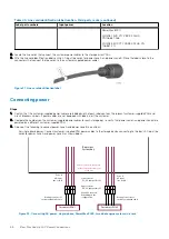
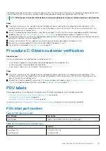
6. Label the PDUs as described in
on page 70.
Procedure C: Obtain customer verification
About this task
Perform this procedure if the three conditions listed below are true:
•
The customer-supplied PDU source cables are already plugged into the storage bay PDU.
•
You have no access to the area below the raised floor.
•
The customer's electrician is not available at the installation site.
Steps
1. Have the customer verify that their electrician has complied with power specifications for voltage levels and redundancy. If the
customer cannot verify this, provide them with a copy of Procedure A. Inform the customer that their array may prematurely shut
down in the event of a site power issue.
2. Record the customer-supplied PDU information (AC source voltage) as described in step 1 of
Procedure A, Task 1: Customer's
on page 63 and label the PDUs as described in
on page 70.
PDU labels
Before applying labels to the sidewalls of the cabinet, one of the following procedures must have been completed:
•
Procedure A: Working with the customer's electrician onsite
on page 63
•
Procedure B: Verify and connect
on page 68
•
Procedure C: Obtain customer verification
on page 69
If necessary, see
Selecting the proper AC power connection procedure
on page 62 to select the correct procedure.
PDU label part number
Table 44. PDU label part number
Part Number
Description
046-008-682
LABEL: CUSTOMER 1P 3P PDU INFO WRITEABLE
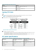
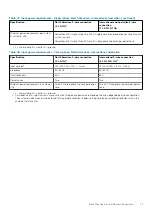
Table 45. PDU label location, Dell EMC racks
Product
Location
PowerMax 2000
PowerMax 8000
OPEN ME FIRST KIT
PN 106-887-026
Best Practices for AC Power Connections
69

