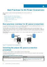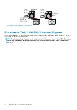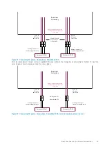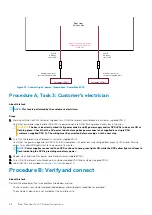
Customer’s PDU 1
Zone B
AC input
line cord B
Mating connector or
customer-supplied cable
Customer’s PDU 2
Zone A
AC input
line cord A
Mating connector or
customer-supplied cable
Rear view
System bay
Cable connectors are shown
as they exit the bottom rear
of the bay.
P1
P1
Figure 35. Connecting AC power, three-phase, PowerMax 8000
Procedure A, Task 3: Customer's electrician
About this task
NOTE:
This task is performed by the customer's electrician.
Steps
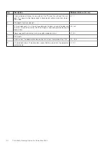
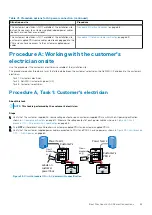
1. Working with the Dell EMC Customer Engineer, turn ON all the relevant circuit breakers in customer-supplied PDU 2.
Verify that only power supply and/or SPS LEDs in power zone A are ON or flashing green in every bay in the array.
CAUTION:
The bay is incorrectly wired if all (power zone A and B) power supply and/or SPS LEDs in a bay are ON or
flashing green. Check that the AC power to both storage bay power zones is not supplied by a single PDU
(customer-supplied PDU 2). The wiring must be corrected before moving on to the next step.
2. Turn OFF the relevant circuit breakers in customer-supplied PDU 2.
Verify that the power supply and/or SPS LEDs that turned green in the previous step changed from green to OFF and/or flashing
yellow. The yellow SPS lights flash for a maximum of 5 minutes.
NOTE:
Power supplies connected to an SPS continue to have green lights ON while the SPS yellow light continues to
flash indicating the SPS is providing on-battery power.
3. Repeat step 1 and step 2 for power zone B and customer-supplied PDU 1.
4. Turn ON all the relevant circuit breakers in customer-supplied PDU 1 and customer-supplied PDU 2.
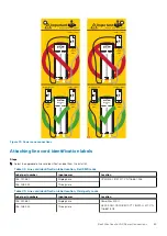
5. Label the PDUs as described in
on page 70.
Procedure B: Verify and connect
About this task
Perform this procedure if the two conditions listed below are true:
•
You have access to customer-supplied, labeled, power cables (beneath raised floor or overhead).
•
The customer's electrician is not available at the installation site.
68
Best Practices for AC Power Connections

