background image

Identify the Failed Hard Drive

To determine which hard drive failed, use the Dell Storage Manager Client.

Steps

1. Use the Dell Storage Manager Client to connect to the Storage Center.
2. Click the 

Hardware

 tab.

3. In the 

Hardware

 tab navigation pane, select the Storage Center.

4. In the 

Hardware Alerts

 area, find the hardware alert that identifies the expansion enclosure with the failed hard drive.

Figure 14. Hardware Alert Identifying the Expansion Enclosure with the Failed Hard Drive

5. In the 

Hardware

 tab navigation pane, expand the expansion enclosure identified in the previous step.

6. Select 

Disks

. The status of each hard drive is displayed in the 

Disks

 tab.

7. Select the failed hard drive. The location of the failed hard drive is displayed in the 

Disk View

 tab.

Figure 15. Front View of the Expansion Enclosure Showing the Failed Hard Drive

Replacing SC4020 Storage System Components

21

Summary of Contents for SC4020

Page 1: ...Dell SC4020 Storage System Owner s Manual ...

Page 2: ...e to hardware or loss of data and tells you how to avoid the problem WARNING A WARNING indicates a potential for property damage personal injury or death Copyright 2017 Dell Inc or its subsidiaries All rights reserved Dell EMC and other trademarks are trademarks of Dell Inc or its subsidiaries Other trademarks may be trademarks of their respective owners 2017 07 Rev I ...

Page 3: ... Indicators 12 SC4020 Storage System Drives 16 SC4020 Storage System Drive Numbering 17 2 Replacing SC4020 Storage System Components 18 Safety Precautions 18 Electrical Safety Precautions 18 Electrostatic Discharge Precautions 18 General Safety Precautions 19 Pre Replacement Procedures 19 Send Diagnostic Data Using Dell SupportAssist 19 Contacting Dell Technical Support 19 Shut Down the Storage Sy...

Page 4: ...3 SC4020 Storage System Technical Specifications 25 Technical Specifications 25 4 Contents ...

Page 5: ...system components Audience The information provided in this manual is intended for use by Dell end users Contacting Dell Dell provides several online and telephone based support and service options Availability varies by country and product and some services might not be available in your area To contact Dell for sales technical support or customer service issues go to www dell com support For cus...

Page 6: ...otes Provides information about Dell Storage Manager releases including new features enhancements fixed issues and open issues Dell TechCenter Provides technical white papers best practice guides and frequently asked questions about Dell Storage products Go to http en community dell com techcenter storage 6 About This Manual ...

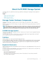
Page 7: ...em contains two redundant power supply cooling fan modules and two storage controllers with multiple I O ports that provide communication with servers and expansion enclosures Switches Dell offers enterprise class switches as part of the total Storage Center solution The SC4020 storage system supports Fibre Channel FC and Ethernet switches which provide robust connectivity to servers and allow for...

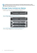
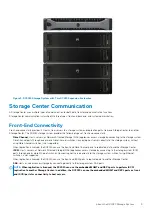
Page 8: ...s A Storage Center with an SC4020 storage system can be deployed in the following configurations An SC4020 storage system deployed without SC200 SC220 expansion enclosures Figure 1 SC4020 Storage System without Expansion Enclosures An SC4020 storage system deployed with one or more SC200 SC220 expansion enclosures Figure 2 SC4020 Storage System with Two SC200 SC220 Expansion Enclosures An SC4020 s...

Page 9: ... to the storage system without using Fibre Channel switches is not supported When replication is licensed the SC4020 can use the front end Fibre Channel ports to replicate data to another Storage Center iSCSI Hosts servers or Network Attached Storage NAS appliances access storage by connecting to the storage system iSCSI ports through one or more Ethernet switches Connecting host servers directly ...

Page 10: ...rt only functions when instructed by Dell Technical Support NOTE Do not throw away the serial cables that come with the SC4020 Keep the serial cables with the SC4020 for troubleshooting purposes SC4020 Storage System Hardware The SC4020 storage system ships with Dell Enterprise Plus drives two redundant power supply cooling fan modules and two redundant storage controllers Each storage controller ...

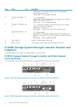
Page 11: ...torage controller indicators and power supply indicators Figure 5 SC4020 Storage System Back Panel View Item Name Icon Description 1 Power supply cooling fan module PSU 2 Contains a 580 W power supply and fans that provide cooling for the storage system 2 Battery backup unit BBU 2 Allows the storage controller to shut down smoothly when a loss of AC power is detected 3 Storage controller 2 Each st...

Page 12: ...n removed a DC or other hardware fault has occurred or the storage system is having a problem communicating with the PSU Blinking amber PSU is in programming mode 8 Power socket 2 Accepts a standard computer power cord 9 Power switch 2 Controls power for the storage system Each PSU has one switch SC4020 Storage System Storage Controller Features and Indicators The SC4020 storage system includes tw...

Page 13: ...utton Not currently used 8 Storage controller fault Off No faults Steady amber Firmware has detected an error Blinking amber Storage controller is performing a POST 9 Recessed reset button Not currently used 10 Identification LED Off Identification disabled Blinking blue for 15 sec Identification is enabled Blinking blue continuously Storage controller shut down to the Advanced Configuration and P...

Page 14: ...5 sec Battery is charging Steady green Battery is ready 2 Battery fault indicator Off No faults Blinking amber Correctable fault detected Steady amber Uncorrectable fault detected replace battery 3 MGMT port Slot 3 Port 1 Ethernet iSCSI port that is typically used for storage system management and access to the BMC NOTE The MGMT port can be used as an iSCSI port for replication to another Storage ...

Page 15: ...ower Steady Amber Link Blinking Green Activity 15 Mini SAS port B Slot 2 Port 2 Back end expansion port B 16 Mini SAS port A Slot 2 Port 1 Back end expansion port A SC4020 Storage System Storage Controller with Front End SAS Ports The following figure shows the features and indicators on a storage controller with front end SAS ports Figure 9 SC4020 Storage System Storage Controller with Four 12 Gb...

Page 16: ...ion LED Off Identification disabled Blinking blue for 15 sec Identification is enabled Blinking blue continuously Storage controller shut down to the Advanced Configuration and Power Interface ACPI S5 state 11 USB port One USB 3 0 connector 12 Diagnostic LEDs 8 Green LEDs 0 3 Low byte hex POST code Green LEDs 4 7 High byte hex POST code 13 Serial port 3 5 mm mini jack Not for customer use 14 Four ...

Page 17: ...eady amber Drive is safe to remove SC4020 Storage System Drive Numbering Drives are numbered from left to right in the SC4020 storage system The Storage Center identifies drives as XX YY where XX is the unit ID of the storage system and YY is the drive position inside the storage system The SC4020 holds up to 24 drives which are numbered from left to right starting from 0 Figure 11 SC4020 Storage ...

Page 18: ... one chassis out of the rack at a time Electrical Safety Precautions Always follow electrical safety precautions to avoid personal injury and damage to the storage system WARNING Disconnect power from the storage system when removing or installing components that are not hot swappable When disconnecting power first power down the storage system using the Dell Storage Manager Client and then unplug...

Page 19: ...e chassis and the chassis cover could become bent Before moving the storage system chassis remove the PSUs to minimize weight Do not remove drives until you are ready to replace them NOTE To ensure proper storage system cooling hard drive blanks must be installed in any hard drive slot that is not occupied Pre Replacement Procedures Perform the procedures described in this section before replacing...

Page 20: ...e 12 Replacing the Front Bezel 5 Hook the right end of the replacement bezel onto the front panel of the storage system 6 Insert the left end of the bezel into the securing slot until the release latch locks into place 7 Secure the bezel with the keylock Replacing Hard Drives The SC4020 storage systems support hot swappable hard drives The SC4020 storage system supports up to 24 2 5 inch hard driv...

Page 21: ...the expansion enclosure with the failed hard drive Figure 14 Hardware Alert Identifying the Expansion Enclosure with the Failed Hard Drive 5 In the Hardware tab navigation pane expand the expansion enclosure identified in the previous step 6 Select Disks The status of each hard drive is displayed in the Disks tab 7 Select the failed hard drive The location of the failed hard drive is displayed in ...

Page 22: ...ier 4 Hard drive slot 4 Press the release button on the replacement hard drive to open the hard drive carrier release handle NOTE Hold the hard drive by the plastic part of the hard drive carrier or the handle 5 Insert the hard drive carrier into the hard drive slot until the carrier make contact with the backplane CAUTION Do not remove the hard drive blanks that are installed in hard drive slots ...

Page 23: ...sist to send diagnostic data to Dell Technical Support Start Up the Storage Controller If the storage controller was previously shut down perform this procedure to start it up Steps 1 Plug the power cables into the power supply cooling fan modules of the storage system 2 Turn on the storage system by pressing the power switches on the power supply cooling fan modules NOTE When the storage system i...

Page 24: ...source 2 Turn on any expansion enclosures attached to the Storage Center NOTE After an expansion enclosure is powered on its ID number is displayed on the back panel If you want the expansion enclosures IDs to appear in sequential order turn on each expansion enclosure one at a time in the order that you want the IDs to appear a Press both power switches on the back of the expansion enclosure at t...

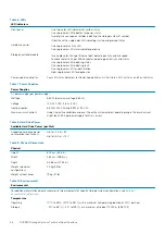
Page 25: ...nt Array of Independent Disks RAID Controller Two hot swappable storage controllers Management RAID management using the Dell Storage Manager Client Table 5 Back Panel Ports Back Panel Ports Connectors per Storage Controllers Fibre Channel iSCSI or SAS connectors Connection to a Fibre Channel fabric iSCSI network or a direct connection to servers with SAS HBAs Ethernet connectors MGMT 1 Gbps or 10...

Page 26: ...ies AC power supply per power supply Wattage 580 W maximum wattage 584 W Voltage 100 240 VAC 7 6 A 3 0 A Heat dissipation 65 W at 230 VAC and 99 W at 115 VAC Maximum inrush current Under typical line conditions and over the entire system ambient operating range the inrush current might reach 45 A per power supply for 40 ms or less Table 8 Hard Drive Power Available Hard Drive Power per Slot Suppor...

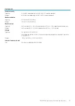
Page 27: ...ine shock 5 G 5 with a pulse duration of 10 ms 10 in operational orientations only Storage Half sine shock 30 G 5 with a pulse duration of 10 ms 10 all sides Altitude Operating 0 m to 3 048 m 0 ft to 10 000 ft For altitudes above 915 m 3 000 ft the maximum operating temperature is derated 1 C per 300 m 1 F per 547 ft Storage 300 m to 12 192 m 1000 ft to 40 000 ft Airborne Contaminant Level Class G...

Reviews: