background image

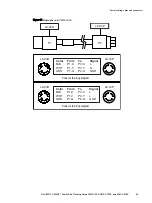
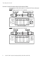
Figure 22 Three-phase, international: E-PCBL3YAG

P1

ABL Sursum - K52S30A or

Hubbell - C530C6S

P2

ABL Sursum - S52S30A or

Hubbell - C530P6S


Wire Color  From 

Hubbell  ABL-Surum 

To 

Hubbell 

ABL-Surum 

BRN 

P1 

R1 

L1 

P2 

R1 

L1 

BLK 

P1 

S2 

L2 

P2 

S2 

L2 

GRY 

P1 

T3 

L3 

P2 

T3 

L3 

BLU 

P1 

P2 

GRN/YEL 

P1 

PE 

P2 

PE 

Power cabling, cords and connectors

64

Dell EMC

 VMAX3

 Family Site Planning Guide VMAX 100K, VMAX 200K, and VMAX 400K

Summary of Contents for VMAX3

Page 1: ...Dell EMC VMAX3 Family Site Planning Guide VMAX 100K VMAX 200K and VMAX 400K Revision 12 0 April 2020 ...

Page 2: ...ICALLY DISCLAIMS IMPLIED WARRANTIES OF MERCHANTABILITY OR FITNESS FOR A PARTICULAR PURPOSE USE COPYING AND DISTRIBUTION OF ANY DELL SOFTWARE DESCRIBED IN THIS PUBLICATION REQUIRES AN APPLICABLE SOFTWARE LICENSE Dell Technologies Dell EMC Dell EMC and other trademarks are trademarks of Dell Inc or its subsidiaries Other trademarks may be the property of their respective owners Published in the USA ...

Page 3: ...re 26 Air volume specifications 26 Temperature altitude and humidity ranges 26 Temperature and humidity range recommendations 26 Air quality requirements 27 Shock and vibration 28 Sound power and sound pressure 28 Hardware acclimation times 29 Optical multimode cables 29 Open systems host and SRDF connectivity 30 Data Center Safety and Remote Support 31 Fire suppressant disclaimer 32 Remote suppor...

Page 4: ...uter room requirements 74 Customer rack requirements 75 Third party racks with vertical PDUs RPQ Required 77 Requirements for third party racks with vertical PDUs rear facing 78 Requirements for third party racks with vertical PDUs inward facing 80 Chassis to chassis grounding 81 Optional kits 83 Overhead routing kit 84 Dispersion kits 84 Securing kits 85 GridRunner kit and customer supplied cable...

Page 5: ...PDU label part numbers 98 Applying PDU labels VMAX3 Family 99 AC power specifications 100 Contents Dell EMC VMAX3 Family Site Planning Guide VMAX 100K VMAX 200K and VMAX 400K 5 ...

Page 6: ...Contents 6 Dell EMC VMAX3 Family Site Planning Guide VMAX 100K VMAX 200K and VMAX 400K ...

Page 7: ...e phase E PW40L730 61 Flying leads three phase international E PC3YAFLE 63 Three phase international E PCBL3YAG 64 Three phase North American Delta E PCBL3DHR 66 Three phase North American Delta E PCBL3DHH 66 Three phase domestic Black and Gray E PCBL3YL23P 68 Location of cabinet ground lugs 70 Customer rack dimension requirements 76 Requirements for customer rack with rear facing vertical PDUs 78...

Page 8: ...Figures 8 Dell EMC VMAX3 Family Site Planning Guide VMAX 100K VMAX 200K and VMAX 400K ...

Page 9: ...agram key 46 Extension cords and connectors options single phase 57 Extension cords and connectors options three phase international Wye 62 Extension cords and connectors options three phase North American Delta 65 Extension cords and connectors options three phase Wye domestic 67 Overhead routing models 84 Dispersion kit model numbers 84 Securing kit models 85 Bottom routing model 86 Procedure op...

Page 10: ...Tables 10 Dell EMC VMAX3 Family Site Planning Guide VMAX 100K VMAX 200K and VMAX 400K ...

Page 11: ...figuration Also listed are documents for external components which interact with your array EMC VMAX3 Family Product Guide for VMAX 100K VMAX 200K VMAX 400K with HYPERMAX OS Provides product information regarding the purchase of a VMAX3 Family 100K 200K 400K Dell EMC VMAX Securing Kit Installation Guide Describes how to install the securing kit on a VMAX3 Family array or VMAX All Flash array Dell ...

Page 12: ...te nonessential information that is omitted from the example Where to get help Support product and licensing information can be obtained as follows Product information Dell EMC technical support documentation release notes software updates or information about Dell EMC products can be obtained at https www dell com support home registration required or https www dellemc com en us documentation vma...

Page 13: ... power 5 0 l Minor edits for consistency and readability l Added new table row and values for Storage time unpowered in the topic Shipping and storage environmental requirements l Added line item to Optical multimode cables topic OM4 cables are used for SRDF connectivity over 16 Gb s Fibre Channel I O modules 4 2 l Added information and diagrams for third party racks with vertical PDUs l Updated h...

Page 14: ...er wants in the data center 3 3 Updates l 3rd party customer rack dimension requirements graphic l Single and dual engine layout graphics 3 2 New NOTICE in Best practices overview for AC power connections 3 1 Update Customer to system 3 phase connectors 3 Update Environmental operating ranges table 2 Update Dual engine layout graphic 1 First release of the VMAX 100K 200K and 400K arrays with EMC H...

Page 15: ...CHAPTER 1 Pre planning tasks This chapter includes l Overview of data center requirements 16 l Tasks to review 16 Dell EMC VMAX3 Family Site Planning Guide VMAX 100K VMAX 200K and VMAX 400K 15 ...

Page 16: ...ndent customer supplied power distribution unit PDU Dell EMC recommends that the customer s electrician be available at the installation site for regular and third party racked arrays Best Practices for AC Power Connections on page 87 provides details For customer supplied third party rack support see the detailed physical requirements in Third Party Racking Option on page 73 The field representat...

Page 17: ...s chapter includes l Delivery arrangements 18 l Pre delivery considerations 18 l Moving up and down inclines 18 l Shipping and storage environmental requirements 19 Dell EMC VMAX3 Family Site Planning Guide VMAX 100K VMAX 200K and VMAX 400K 17 ...

Page 18: ...delivery Pre delivery considerations Take into account the following considerations prior to the delivery at your site l Weight capacities of the loading dock tailgate and service elevator if delivery is to a floor other than the receiving floor l Length and thickness of covering required for floor protection l Equipment ramp availability if the receiving floor is not level with computer room floo...

Page 19: ...vironmental requirements Condition Setting Ambient temperature 40 to 149 F 40 to 65 C Temperature gradient 43 2 F hr 24 C hr Relative humidity 10 to 90 noncondensing Storage time unpowered Recommendation Do not exceed 3 consecutive months of unpowered storage Delivery and transportation Dell EMC VMAX3 Family Site Planning Guide VMAX 100K VMAX 200K and VMAX 400K 19 ...

Page 20: ...Delivery and transportation 20 Dell EMC VMAX3 Family Site Planning Guide VMAX 100K VMAX 200K and VMAX 400K ...

Page 21: ...nsumption and heat dissipation 23 l Airflow 25 l Air volume air quality and temperature 26 l Shock and vibration 28 l Sound power and sound pressure 28 l Hardware acclimation times 29 l Optical multimode cables 29 Dell EMC VMAX3 Family Site Planning Guide VMAX 100K VMAX 200K and VMAX 400K 21 ...

Page 22: ...form the evaluation of RFI field strength and address the mitigation efforts if high levels of RFI are suspected The ambient RFI field strength is inversely proportional to the distance and power level of the emitting device Recommended minimum distance from RF emitting device The following table provides the recommended minimum distances between Dell EMC arrays and RFI emitting equipment Use thes...

Page 23: ...on 26 C 35 C kVA Maximum heat dissipation 26 C 35 C Btu Hr Maximum total power consumption 26 C 35 C kVA Maximum heat dissipation 26 C 35 C Btu Hr System bay 1 Single engine 8 27 10 8 28 201 36 828 8 37 10 9 28 542 37 169 8 57 11 1 29 224 37 851 System bay 2 Single engineb 8 13 10 4 27 723 35 464 8 33 10 6 28 405 36 146 8 43 10 7 28 746 36 487 System bay 1 Dual engine 6 44 8 8 21 960 30 008 6 74 9...

Page 24: ...tures increase the adaptive cooling increases the fan speeds with the resulting platform power increasing up to the maximum values shown below These values along with the SPS recharge power consumption contribute to the maximum system power consumption values over 35 C shown in Table 6 on page 23 l DAE120 2 5 Drives 305VA 1024 BTU hr l DAE60 3 5 Drives 265VA 904 BTU hr l Engine 80VA 273 BTU hr Spe...

Page 25: ...ing the exhaust air completely and connecting ducts directly to a CRAC unit or to the outside Best practice is to place a perforated floor tile in front of each bay to allow adequate cooling air supply when installing on a raised floor The following figure shows typical airflow in a hot aisle cold aisle environment Figure 1 Typical airflow in a hot cold aisle environment 5 6 5 4 4 8 7 9 9 1 1 2 2 ...

Page 26: ... 7 500 ft 10 35 C 50 95 F at 950 m 3 317 ft Operating temperature excursion limit 24 hours annually 32 50 C 50 122 F at 2 286 m 7 500 ft Operating altitude maximum derating 3 048 m 10 000 ft derate 1 1 C per 305 m above 2 286 m Operating humidity range 20 to 80 RH non condensing Operating temperature rate of change 20 C hour a These values apply to the inlet temperature of any component within the...

Page 27: ...ers from entering the facility The allowable relative humidity level is 20 80 non condensing however the recommended operating environment range is 40 55 For data centers with gaseous contamination such as high sulfur content lower temperatures and humidity are recommended to minimize the risk of hardware corrosion and degradation In general the humidity fluctuations within the data center should ...

Page 28: ...0 Grms 5 500Hz 30 minutes Operational random vibration 21 Grms 5 500Hz 10 minutes Packaged system condition Transportation shock 10 G s 12 ms duration Transportation random vibration 1 15 Grms 1 hour Frequency range 1 200 Hz Sound power and sound pressure The following table provides the sound power and sound pressure levels Table 12 Sound power and sound pressure levels A weighted Configuration S...

Page 29: ...low an additional 8 hours to stabilize l Systems and components must not experience changes in temperature and humidity that are likely to cause condensation to form on or in that system or component Do not exceed the shipping and storage temperature gradient of 45 F hr 25 C hr Optical multimode cables Optical multimode 3 OM3 and optical multimode 4 OM4 cables are available for open systems host a...

Page 30: ...st and SRDF connectivity The following table provides the OM3 and OM4 cables Table 13 OM3 and OM4 Fibre cables 50 125 micron optical cable Model number Description SYM OM3 1M LC LC 1 meter SYM OM3 3M LC LC 3 meter SYM OM3 5M LC LC 5 meter SYM OM3 10M LC LC 10 meter SYM OM3 30M LC LC 30 meter SYM OM3 50M LC LC 50 meter SYM OM3 100M LC LC 100 meter SYM OM4 1M LC LC 1 meter SYM OM4 3M LC LC 3 meter S...

Page 31: ...CHAPTER 4 Data Center Safety and Remote Support This chapter includes l Fire suppressant disclaimer 32 l Remote support 32 Dell EMC VMAX3 Family Site Planning Guide VMAX 100K VMAX 200K and VMAX 400K 31 ...

Page 32: ...nd remote support solution Secure Remote Services is the preferred method of connectivity Two connections with Secure Remote Services are recommended for connection to the redundant management module control station MMCS Customers of Secure Remote Services must provide the following l An IP network with Internet connectivity l Capability to add Gateway Client servers and Policy Manager servers to ...

Page 33: ...cal weight and space This chapter includes l Floor load bearing capacity 34 l Raised floor requirements 34 l Physical space and weight 35 Dell EMC VMAX3 Family Site Planning Guide VMAX 100K VMAX 200K and VMAX 400K 33 ...

Page 34: ...or requirements Best practice is to use 24 x 24 inch heavy duty concrete filled steel floor tiles If a different size or type of tile is used the customer must ensure that the tiles have a minimum load rating that is sufficient for supporting the storage array weight Ensure proper physical support of the system by following requirements that are based on the use of 24 x 24 in 61 x 61 cm heavy duty...

Page 35: ...he physical space maximum weights and clearance for service Table 14 Space and weight requirements Bay configurations a Heightb in cm Width in cm Depthc in cm Weight max lbs kg System bay single engine 75 190 24 61 47 119 2065 937 System bay dual engine 75 190 24 61 47 119 1860 844 a Clearance for service airflow is the front at 42 in 106 7 cm front and the rear at 30 in 76 2 cm b An additional 18...

Page 36: ...Physical weight and space 36 Dell EMC VMAX3 Family Site Planning Guide VMAX 100K VMAX 200K and VMAX 400K ...

Page 37: ... Bays This chapter includes l System bay layouts 38 l Dimensions for array layouts 44 l Tile placement 45 l Caster and leveler dimensions 45 Dell EMC VMAX3 Family Site Planning Guide VMAX 100K VMAX 200K and VMAX 400K 37 ...

Page 38: ...hernet cable bundles that allow 82 ft 25 m of separation between system bay 1 and system bays 2 through 8 Dispersed system bays require dispersed cable and optics kits and one set of side skins for each dispersed system bay in the configuration l Adjacent and dispersed bays mixed layouts allow both adjacent and dispersed layout of either single or dual engine arrays with adjacent and dispersed bay...

Page 39: ...e array Figure 2 Adjacent layout single engine array System bay 1 System bay 2 System bay 3 System bay 4 System bay 5 System bay 6 System bay 7 System bay 8 Engine 1 Engine 2 Engine 3 Engine 4 Engine 5 Engine 6 Engine 7 Engine 8 R1 R2 R3 R4 R5 R6 R7 00 Bay position 2 3 1 Table 15 Adjacent layout diagram key Description 1 VMAX 100K 2 VMAX 200K 3 VMAX 400K Position Bays Dell EMC VMAX3 Family Site Pl...

Page 40: ... dual engine arrays by model type Figure 3 Adjacent layout dual engine array System bay 1 System bay 2 Engine 1 Engine 2 Engine 4 Engine 3 00 R1 System bay 3 System bay 4 Engine 5 Engine 7 Engine 8 Engine 6 R2 R3 Bay position 2 3 1 Table 16 Adjacent layout diagram key Description 1 VMAX 100K 2 VMAX 200K 3 VMAX 400K Position Bays 40 Dell EMC VMAX3 Family Site Planning Guide VMAX 100K VMAX 200K and ...

Page 41: ...ed layout Figure 4 Dispersed layout single engine array System bay 1 System bay 3 System bay 4 System bay 5 System bay 6 System bay 8 System bay 2 System bay 7 Engine 3 Engine 4 Engine 5 Engine 6 Engine 7 Engine 2 Engine 1 Engine 8 Position Bays Dell EMC VMAX3 Family Site Planning Guide VMAX 100K VMAX 200K and VMAX 400K 41 ...

Page 42: ...spersed layout Figure 5 Dispersed layout dual engine front view System bay 1 Engine 7 Engine 2 Engine 1 Engine 8 Engine 5 Engine 6 Engine 3 Engine 4 System Bay 2 System Bay 1 System Bay 3 System Bay 4 Position Bays 42 Dell EMC VMAX3 Family Site Planning Guide VMAX 100K VMAX 200K and VMAX 400K ...

Page 43: ...xed layout single engine array System bay 1 System bay 2 System bay 4 System bay 3 Engine 3 Engine 1 Engine 2 Engine 4 Initial install Upgrade 00 R1 R2 Bay position Initial install The following figure shows a dual engine array with a mixed layout Position Bays Dell EMC VMAX3 Family Site Planning Guide VMAX 100K VMAX 200K and VMAX 400K 43 ...

Page 44: ...aised floors cables are routed overhead An overhead routing bracket is provided to allow easier access of overhead cables into the bay l On raised floors cables are routed across the subfloor beneath the tiles l Ensure there is a service area of 42 in 106 cm for the front and 30 in 76 cm for the rear of each system bay The following figure shows the layout dimensions Figure 8 Layout dimensions VMA...

Page 45: ...nformation for all VMAX3 arrays with doors Figure 9 Placement with floor tiles VMAX3 Family Rear A A System bay System bay A System bay A System bay A A A System bay A System bay System bay System bay Front F l o o r T i l e Caster and leveler dimensions The bottom of each bay includes four caster wheels The front wheels are fixed the two rear casters swivel in a 1 75 in diameter Swivel position o...

Page 46: ...0 Table 17 Caster and leveler dimensions diagram key Description 1 Minimum 17 102 and maximum 20 58 distances based on the swivel position of the caster wheel 2 Right front corner detail Dimension 3 628 to the center of caster wheel from surface 3 Diameter 1 750 of caster wheel swivel 4 Outer surface of rear door 5 6 Diameter 1 75 of swivel see detail 3 7 Bottom view of leveling feet Position Bays...

Page 47: ...ance based on swivel position of the caster wheel 9 Minimum 30 870 distance based on swivel position of the caster wheel 10 Distance 3 620 to the center of the caster wheel from the surface see detail 2 Position Bays Dell EMC VMAX3 Family Site Planning Guide VMAX 100K VMAX 200K and VMAX 400K 47 ...

Page 48: ...Position Bays 48 Dell EMC VMAX3 Family Site Planning Guide VMAX 100K VMAX 200K and VMAX 400K ...

Page 49: ...stribution unit 50 l Wiring configurations 52 l Power interface 55 l Customer input power cabling 55 l Best practices Power configuration guidelines 55 l Power extension cords connectors and wiring 56 Dell EMC VMAX3 Family Site Planning Guide VMAX 100K VMAX 200K and VMAX 400K 49 ...

Page 50: ...are divided into six banks with each bank consisting of four IEC 60320 C13 individual AC outlets l Each bank of outlets is connected to individual branch circuits that are protected by a single two pole 20 Amp circuit breaker l Depending on which PDU option selected there is a different input connector for each PDU If the customer requires power to be supplied from overhead Dell EMC recommends rep...

Page 51: ...ed wire bales rear view Note Utilize proper strain relief methods when customer provided power drops are located overhead or wall mounted Power cabling cords and connectors Dell EMC VMAX3 Family Site Planning Guide VMAX 100K VMAX 200K and VMAX 400K 51 ...

Page 52: ... power supply 15 4 57m extension cables are provided Single phase wiring configuration Figure 13 Single phase horizontal 2U PDU internal wiring 1 2 3 15 14 16 18 19 21 20 20A CB4 22 20A CB1 20A CB5 20A CB6 23 20A CB2 20A CB3 L1 L1 L1 L1 L1 L1 4 5 6 7 8 9 10 11 13 L N L N L N L1 10AWG L2 10 AWG 10 AWG N L L N L N P1 L2 L2 L2 L2 L2 L2 G G 10 AWG G L1 10AWG L2 10 AWG G 10 AWG Green L1 10AWG L2 10 AWG...

Page 53: ...1 L2 L2 L2 L2 L3 L3 L3 L3 L1 X 8AWG Black wire L2 Y 8 AWG White wire L3 Z 8 AWG Red wire G 8 AWG Green 8 AWG P1 14 13 15 17 18 20 19 21 22 12 L N L N L N L N L N 16 L N 1 2 3 4 5 6 7 8 9 10 11 N L L N L N N L L N L N 23 24 Hubbell CS 8365L or equivalent x 2 Power cabling cords and connectors Dell EMC VMAX3 Family Site Planning Guide VMAX 100K VMAX 200K and VMAX 400K 53 ...

Page 54: ...CB3 L1 L1 L2 L2 L3 L3 L1 X Brown L2 Y Black L3 Z Gray Green yellow 10 AWG G N N N N N N N Blue 14 13 15 17 18 20 19 21 22 12 L N L N L N L N L N 16 L N 1 2 3 4 5 6 7 8 9 10 11 N L L N L N N L L N L N 23 24 ABL SURSUM S52S30A or equivalent x 2 Power cabling cords and connectors 54 Dell EMC VMAX3 Family Site Planning Guide VMAX 100K VMAX 200K and VMAX 400K ...

Page 55: ...omplete power provisioning with the data center prior to connecting power to the array l The customer s electrician or facilities representative must verify that the AC voltage is within specification at each of the power drops being fed to each product bay l All of the power drops should be labeled to indicate the source of power PDU and the specific circuit breakers utilized within each PDU n Co...

Page 56: ...offer different interface connector options The selected cords are used to interface between the customer s power source and each PDU connection The number of cords needed is determined by the number of bays in the array and the type of input power source used single phase or three phase Power cabling cords and connectors 56 Dell EMC VMAX3 Family Site Planning Guide VMAX 100K VMAX 200K and VMAX 40...

Page 57: ...eptacle Customer PDU receptacle NEMA L6 30 E PW40U US 038 003 438 BLK 15FT 038 003 898 GRY 15FT 038 003 479 BLK 21FT 038 003 794 GRY 21FT NEMA L6 30R NEMA L6 30P NEMA L6 30R E PW40URUS 038 003 441 BLK 15FT 038 003 901 GRY 15FT 038 003 482 BLK 21FT 038 003 797 GRY 21FT NEMA L6 30R Russellstoll 3750DP Russellstoll 9C33U0 E PW40UIEC3 CAUTION The single phase line voltage must be below 264VAC to use t...

Page 58: ...these cable assemblies 038 004 301 BLK 15FT 038 004 302 GRY 15FT 038 004 303 BLK 21FT 038 004 304 GRY 21FT NEMA L6 30R NEMA L7 30P NEMA L7 30R a Six 6 plugs per system bay b Two 2 cords per model cord length of 15 feet 4 57 meters c The Dell EMC ordering system defaults to one of the extension cord models based on the country of installation The default value can be overridden in the Dell EMC orde...

Page 59: ... BLK P1 X P2 X L WHT P1 Y P2 Y N GRN P1 G P2 G GND X Y G L6 30R L6 30P X Y G Power cord wiring diagram Color From To Signal BLK P1 X P2 X L WHT P1 Y P2 Y L GRN P1 G P2 G GND X Y G L6 30R L6 30P Power cabling cords and connectors Dell EMC VMAX3 Family Site Planning Guide VMAX 100K VMAX 200K and VMAX 400K 59 ...

Page 60: ... wiring diagram L6 30R L1 L2 G 3750DP Figure 18 Single phase E PW40UIEC3 X Y G P1 P2 L6 30R 332P6W G Y X Color From To Signal BRN P1 X P2 X L BLU P1 Y P2 Y N GRN YEL P1 G P2 G GND X Y G Power cord wiring diagram L6 30R 332P6W X Y G Color From To Signal BLK P1 X P2 X L WHT P1 Y P2 Y L GRN YEL P1 G P2 G GND Power cord wiring diagram L6 30R 332P6W G Y X G Y X Power cabling cords and connectors 60 Del...

Page 61: ...P2 E GND X Y G Power cord wiring diagram L6 30R 56PA332 G Y X G Y X X Y G Figure 20 Single phase E PW40L730 L6 30R L7 30P P1 P2 Color Signal P1 P2 BLK L X Brass WHT N Y W Silver GRN YEL GND GND GND X Y G Power cord wiring diagram L6 30R L7 30P Color Signal P1 P2 BLK L X Brass WHT L Y W Silver GRN YEL GND GND GND X Y G Power cord wiring diagram L6 30R L7 30P Power cabling cords and connectors Dell ...

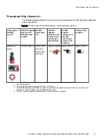
Page 62: ...6S E PC3YAFLEc 038 004 572 BLK 15FT 038 004 573 GRY 15FT ABL Sursum K52S30A or Hubbell C530C6S Flying Leads International Determined by customer E PCBL3YAG 038 004 574 BLK 15FT 038 004 575 GRY 15FT ABL Sursum K52S30A or Hubbell C530C6S ABL Sursum S52S30A or Hubbell C530P6S ABL Sursum K52S30A or Hubbell C530C6S a Two 2 plugs per bay Up to four 4 plugs if a third party or second system is in the rac...

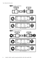
Page 63: ...on Figure 21 Flying leads three phase international E PC3YAFLE P1 Shrink tubing ABL Sursum K52S30A or Hubbell C530C6S Wire Color From Hubbell Connector ABL Sursum Connector TO BRN P1 R1 L1 X L1 BLK P1 S2 L2 Y L2 GRY P1 T3 L3 Z L3 BLU P1 N N W N GRN YEL P1 G PE GND Power cabling cords and connectors Dell EMC VMAX3 Family Site Planning Guide VMAX 100K VMAX 200K and VMAX 400K 63 ...

Page 64: ...S52S30A or Hubbell C530P6S Wire Color From Hubbell ABL Surum To Hubbell ABL Surum BRN P1 R1 L1 P2 R1 L1 BLK P1 S2 L2 P2 S2 L2 GRY P1 T3 L3 P2 T3 L3 BLU P1 N N P2 N N GRN YEL P1 G PE P2 G PE Power cabling cords and connectors 64 Dell EMC VMAX3 Family Site Planning Guide VMAX 100K VMAX 200K and VMAX 400K ...

Page 65: ...eptacle Customer PDU receptacle Hubbell CS 8365C E PCBL3DHRc 038 003 272 BLK 15FT 038 003 789 GRY 15FT Hubbell CS 8364C Russellstoll 9P54U2 Russellstoll 9C54U2d E PCBL3DHH 038 003 271 BLK 15FT 038 003 788 GRY 15FT Hubbell CS 8364C Hubbell CS 8365C Hubbell CS 8364C a Two 2 plugs per bay b Two 2 cords per model cord length of 15 feet 4 57 meters c The Dell EMC ordering system defaults to one of the ...

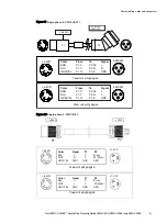
Page 66: ...4U2 CS8364 9P54U2 Color BLK WHT RED GRN From P1 X P1 Y P1 Z P1 G To P2 X P2 Y P2 Z P2 G Signal L1 L2 L3 GND X Y Z X Y Z Power cord wiring diagram Figure 24 Three phase North American Delta E PCBL3DHH P1 P2 CS8364 CS8365 CS8364 CS8365 Color BLK WHT RED GRN From P1 X P1 Y P1 Z P1 G To P2 X P2 Y P2 Z P2 G Signal L1 L2 L3 GND Y Z Z X X Y Power cabling cords and connectors 66 Dell EMC VMAX3 Family Site...

Page 67: ...2 connecting to customer PDU receptacle Customer PDU receptacle ABL Sursum S52 30 E PCBL3YL23P c d 038 004 305 BLK 15FT 038 004 306 GRY 15FT Hubbell C530C6S NEMA L22 30P NEMA L22 30R a Two 2 plugs per bay b Two 2 cords per model cord length of 15 feet 4 57 meters c The Dell EMC ordering system defaults to one of the extension cord models based on the country of installation The default value can b...

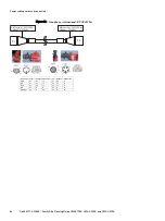
Page 68: ... NEMA P1 P2 L22 30P Color From P1 To P2 Signal BLK1 P1 R1 P2 X L1 BLK2 P1 S2 P2 Y L2 BLK3 P1 T3 P2 Z L3 BLK4 P1 N P2 N N GRN YLW P1 G P2 G GND C530C6S L22 30P Black 15 ft Gray 15 ft P1 P2 Color From P1 To P2 Signal BRN P1 R1 P2 X L1 BLK P1 S2 P2 Y L2 GRAY P1 T3 P2 Z L3 BLUE P1 N P2 N N GRN YLW GND GND GND C530C6S L22 30P Power cabling cords and connectors 68 Dell EMC VMAX3 Family Site Planning Gui...

Page 69: ... for single bay configurations Chassis to chassis grounding is required for systems with multiple bays l Grounding requirements 70 l Grounding a single bay 70 l Chassis to chassis grounding 71 Dell EMC VMAX3 Family Site Planning Guide VMAX 100K VMAX 200K and VMAX 400K 69 ...

Page 70: ...d within the cabinet is grounded through the AC power cables and connectors In general supplemental grounding is not required for a single bay If your site requires external grounding for example to a common grounding network beneath the site floor you can use the grounding lugs provided on each of the cabinet s bottom supports Figure 26 Location of cabinet ground lugs CL4827 0 4 6 0 0 3 3 5 0 Gro...

Page 71: ...traps for both the front and rear of the cabinets Both straps must be installed to provide chassis to chassis grounding In customer rack systems mechanisms for tying racks together to provide the ground connection can vary based on the rack provided by the customer and site facility preference PN 106 562 209 is a rack to rack grounding kit for Dell EMC racks The grounding kit may or may not work o...

Page 72: ...Grounding Racks 72 Dell EMC VMAX3 Family Site Planning Guide VMAX 100K VMAX 200K and VMAX 400K ...

Page 73: ...apter includes l Computer room requirements 74 l Customer rack requirements 75 l Third party racks with vertical PDUs RPQ Required 77 l Chassis to chassis grounding 81 Dell EMC VMAX3 Family Site Planning Guide VMAX 100K VMAX 200K and VMAX 400K 73 ...

Page 74: ... of cables and connections do not move racks that are secured bolted together after installation l A minimum of 42 inches 107 cm front and 30 inches 76 cm rear clearance is required to provide adequate airflow and to allow for system service Third Party Racking Option 74 Dell EMC VMAX3 Family Site Planning Guide VMAX 100K VMAX 200K and VMAX 400K ...

Page 75: ...able space in different bay or to a different location within the same bay n System must be properly positioned in accordance with physical placement rules l Internal depth of at least 43 inches 109 cm with the front and rear doors closed This measurement is from the front surface of the NEMA rail to the rear door l Round or square channel openings must support M5 screws that secure rails and comp...

Page 76: ...ion a distance between front surface of rack post and NEMA rail b distance between NEMA rails 24 60 96 cm recommended up to 34 86 36 cm allowed c distance between rear NEMA rails to interior surface of rear door Minimum requirement 19 48 26 cm d If a front door exists distance between inner front surface of the front door and the front NEMA rail e distance between rear surface of rack post to inne...

Page 77: ...owing requirements n At a minimum a total of 24 power outlets must be provided The outlets are divided into six banks with each bank consisting of four IEC 60320 C13 individual AC outlets n Each bank of outlets is connected to individual branch circuits that are protected by a single two pole 20 Amp circuit breaker n The PDU capacity should exceed the power requirements shown in the Power Calculat...

Page 78: ... c Dim Label Description a distance between front surface of rack post and NEMA rail b distance between NEMA rails 24 60 96 cm recommended up to 34 86 36 cm allowed c distance between rear NEMA rails to exterior rear surface of rack d If a front door exists distance between inner front surface of the front door and the front NEMA rail e distance between rear surface of rack post to inner surface o...

Page 79: ...y other parallel surface that may interfere with the power cables Note Dimension k is dependent on this value k min depth b c Where l j 6 15 24cm is a requirement l IF j is 6 15 24cm min rack depth 43 109 2cm l IF j is 6 15 24cm min rack depth 43 109 2cm distance required to make j 6 15 24cm pw PDU width Third Party Racking Option Dell EMC VMAX3 Family Site Planning Guide VMAX 100K VMAX 200K and V...

Page 80: ...in f 19 48 26 cm 2g min e Rear Door Rear 19 NEMA 48 26 cm cb g PDU c h 43 109 2 cm min Min depth Rack depth a b c Dim Label Description a distance between front surface of rack post and NEMA rail b distance between NEMA rails 24 60 96 cm recommended up to 34 86 36 cm allowed c distance between rear NEMA to exterior rear surface of rack cb Cable Bend 4 minimum 10 156 cm d If a front door exists dis...

Page 81: ...ultiple bay Dell EMC rack systems use the rack to rack grounding kit PN 106 562 209 to provide chassis to chassis grounding The kit provides straps for both the front and rear of the cabinets Both straps must be installed to provide chassis to chassis grounding In customer rack systems mechanisms for tying racks together to provide the ground connection can vary based on the rack provided by the c...

Page 82: ...Third Party Racking Option 82 Dell EMC VMAX3 Family Site Planning Guide VMAX 100K VMAX 200K and VMAX 400K ...

Page 83: ...ts This chapter includes l Overhead routing kit 84 l Dispersion kits 84 l Securing kits 85 l GridRunner kit and customer supplied cable trough 85 Dell EMC VMAX3 Family Site Planning Guide VMAX 100K VMAX 200K and VMAX 400K 83 ...

Page 84: ... dispersion kits include a 82 foot 25 m optical cable and optics for the dispersed engine When installing a dispersed layout side skins E SKINS are required The following table lists model numbers for new installations and upgrades Table 23 Dispersion kit model numbers Model Description E DSOPTICE2 VMAX VG SYS BAY 2 DSP CBLOPTICS KIT E DSOPTICE2U VMAX VG SYS BAY 2 DSP CBLOPTICS KIT UPG E DSOPTICE3...

Page 85: ...llation Guide provides installation instructions Table 24 Securing kit models Model Description E SECURE Secure kit for single bay E SECUREADD Secure kit for joining bays GridRunner kit and customer supplied cable trough The Dell EMC GridRunner bottom routing kit E BOT KIT and customer supplied cable troughs can help organize and protect subfloor cables that connect separated bays GridRunners redu...

Page 86: ...model Model Description E BOT KIT a Bottom routing kit a GridRunner basket for supporting cables beneath the floor for dispersed bays Optional kits 86 Dell EMC VMAX3 Family Site Planning Guide VMAX 100K VMAX 200K and VMAX 400K ...
Page 87: ...l Selecting the proper AC power connection procedure 89 l Procedure A Working with the customer s electrician onsite 90 l Procedure B Verify and connect 97 l Procedure C Obtain customer verification 98 l PDU labels 98 l AC power specifications 100 Dell EMC VMAX3 Family Site Planning Guide VMAX 100K VMAX 200K and VMAX 400K 87 ...

Page 88: ...dependent AC power is not available there is a higher risk of data unavailability should a power failure occur including individual phase loss occurring in both power zones Before connecting external AC power to storage bays verify that the bays have been placed in their final position as explained in the installation guide Figure 31 Two independent customer supplied PDUs Customer s PDU 1 Customer...

Page 89: ...customer s electrician onsite on page 90 This procedure assures fault tolerant power in the storage array The customer s electrician is NOT available at the installation site but you have access to customer supplied labeled power cables beneath a raised floor or overhead Procedure B Verify and connect on page 97 The customer s electrician is NOT available at the installation site customer supplied...

Page 90: ...dure requires three basic tasks that alternate between the customer s electrician the Dell EMC CE and back to the customer s electrician l Task 1 Customer s electrician l Task 2 Dell EMC Customer Engineer CE l Task 3 Customer s electrician Best Practices for AC Power Connections 90 Dell EMC VMAX3 Family Site Planning Guide VMAX 100K VMAX 200K and VMAX 400K ...

Page 91: ...t breakers ON AC power within specification Customer s PDU 1 Customer s PDU 2 Circuit breakers on Circuit breakers on Circuit breakers Numbers 27 28 29 30 Circuit breakers Numbers 8 9 10 11 Labels on customer power lines Power feed 1 Power feed 2 PDU 1 CB 28 PDU 2 CB 9 Voltmeter TYPE PM89 CLASS 25 01 0 100 240300 V Voltmeter TYPE PM89 CLASS 25 01 0 100 240300 V Figure 33 Circuit breakers OFF No AC...

Page 92: ... 4 5 6 1 2 3 4 5 6 Procedure 1 Confirm that the customer supplied power cables are labeled and that each label contains the relevant customer supplied PDU and circuit breaker numbers If power cables are not equipped with labels alert the customer 2 Compare the numbers on the customer supplied power cables for each Dell EMC bay to verify that power zone A and power zone B are powered by a different...

Page 93: ...le connectors are shown as they exit the bottom rear of the bay Rear view System bay Zone B PDU Left Zone A PDU Right EMC supplied power cable and connector from the PDU P1 P2 P3 P1 P2 P3 P2 and P3 used depending on configuration l For three phase power Connect customer supplied PDU power cables to the Dell EMC bay by connecting to the bay s AC input cables for power zone A and power zone B as sho...

Page 94: ...ay Zone B PDU Left Zone A PDU Right EMC supplied power cable and connector from the PDU Zone B PDU Left Zone A PDU Right Cable connectors are shown as they exit the bottom rear of the bay NOTICE Do not connect Dell EMC bay power zone A and power zone B to the same customer supplied PDU The customer will lose power redundancy and risk Data Unavailability DU if the PDU fails or is turned off during ...

Page 95: ...CBs Customer s Power Source 2 Circuit Breakers CBs t n a t r o p m I l a u n a m n o i t c u r t s n i o t r e f e R Zone B Zone A Rear View SYSTEM Customer s Power Source 1 Circuit Breakers CBs Zone B Zone A Rear View SYSTEM Customer s Power Source 1 Circuit Breakers CBs Customer s Power Source 2 Circuit Breakers CBs 046 001 749_01 Best Practices for AC Power Connections Dell EMC VMAX3 Family Sit...

Page 96: ...corrected before moving on to the next step 2 Turn OFF the relevant circuit breakers in customer supplied PDU 2 Verify that the power supply and or SPS LEDs that turned green in the previous step changed from green to OFF and or flashing yellow The yellow SPS lights flash for a maximum of 5 minutes Note Power supplies connected to an SPS continue to have green lights ON while the SPS yellow light ...

Page 97: ...oltage levels and redundancy If the customer cannot verify this provide them with a copy of Procedure A Inform the customer that their array may prematurely shut down in the event of a site power issue 2 Access the labeled power cables beneath raised floor or overhead to verify that the customer supplied power cables are properly labeled as shown in Figure 33 on page 91 and described in Procedure ...

Page 98: ...nformation AC source voltage as described in step 1 of Procedure A Task 1 Customer s electrician on page 91 and label the PDUs as described in PDU labels on page 98 PDU labels Before applying labels to the PDUs one of the following procedures must have been completed l Procedure A Working with the customer s electrician onsite on page 90 l Procedure B Verify and connect on page 97 l Procedure C Ob...

Page 99: ...he PDU enclosure for side A and B Figure 38 PDU label single phase and three phase Customer PDU Information Power Zone B PDU Panel CB s P1 P2 P3 Power Zone A PDU Panel CB s P1 P2 P3 Figure 39 Label placement Customer PDU Information Rear View Zone A PDU label Zone B PDU label Best Practices for AC Power Connections Dell EMC VMAX3 Family Site Planning Guide VMAX 100K VMAX 200K and VMAX 400K 99 ...

Page 100: ...s Three phase North American International Australian Specification North American 4 wire connection 3 L 1 G a International 5 wire connection 3 L 1 N 1 G a Input voltageb 200 240 VAC 10 L L nom 220 240 VAC 10 L N nom Frequency 50 60 Hz 50 60 Hz Circuit breakers 50 A 32 A Power zones Two Two Minimum power requirements at customer site One 50 A three phase line cord per power zone One 32 A three ph...

Reviews: