12
EMC VNXe3100/VNXe3150 — Adding a Second Storage Processor
Troubleshooting Notes
Troubleshooting Notes
This section describes troubleshooting steps to follow in the event that you are having
problems. Note that these troubleshooting steps apply
before
you validate the upgrade
and reboot the system to normal mode with the service script svc_change_config --commit
(see
Task 8
“Validate the upgrade and reboot the system” on page 10
); after that time,
please contact your service provider directly for assistance with your dual storage
processor system.
Problem: Running svc_change_config in normal mode, the following message is
displayed:
The upgrade cannot proceed. Please run the system health check
from the management application to determine the problem.
Solution: The service script detected a problem that prevents the upgrade. Running the
system health check from the management application is the best approach to diagnose
the problem.
Problem: After inserting an SP and restoring power, the SP does not reach service mode
(indicated by the fault LED alternating blue and amber); the fault LED remains solid amber.
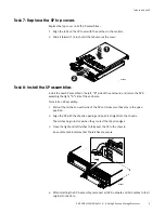
Solution: The SP must be inserted firmly so that it will "seat" properly. Using the orange
release levers on the faulted SP, reseat the SP by sliding the SP out of the enclosure a few
inches and pushing it back in, being certain that the latches are fully closed to properly
seat the SP. Refer to
“Task 8: Install the SP assemblies” on page 9
.
Problem: When running svc_change_config --commit you see the following message:
You cannot commit the upgrade. Please verify that both SPs are
inserted, and both are running in service mode.
Solution: It takes somewhat longer for a newly inserted storage processor to complete
initialization and to reach service mode, than for the original storage processor, SP A. If
the fault LED on the back of SP B (the new storage processor) is not alternating amber and
blue after 20 minutes, then attempt to reinstall the storage processors (SP A and SP B):
1. Release the cable retention bail and unplug the power cord from each power supply.
2. Ensure all cables are labeled so they can be reconnected correctly.
3. Locate the two orange release levers on the SP B latches; squeeze the levers to release
the latches; and, then pull the latches outward.
4. Pull out the latches until they are fully extended and SP B is released from its
enclosure.
5. Use the latches to partially slide SP B from its enclosure.
When SP B is about half-way out of its enclosure, use both hands to support the
assembly and draw it fully out of the enclosure.
6. Follow steps 1-5 on SP A. Make sure to mark SP A with tape or some other means to
ensure that you return it to its original slot, and label all cables to ensure they are
reconnected correctly.
7. Remove and then reinstall the memory on SP A. Refer to
8. Remove and then reinstall the memory on SP B.


