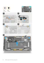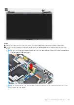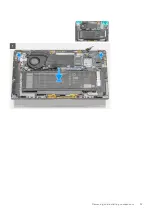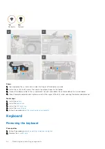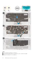
Steps
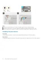
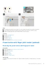
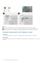
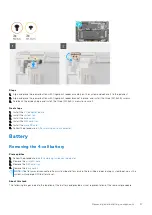
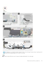
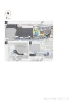
1. Flip the system board over and connect the I/O daughter board data cable.
2. Align and place the system board on the palmrest and keyboard assembly.
3. Replace the five (M1.6x3.5) screws to secure the system board to the palmrest and keyboard assembly .
4. Replace the three (M1.6x3.5) screws to secure the USB Type-C bracket to the system board.
5. Connect the I/O daughter board data FPC cable to the connector on the I/O daughter board.
6. Connect the USH daughter board FFC cable, WWAN Darwin cable, and Touchpad FPC to the connector on the system
board.
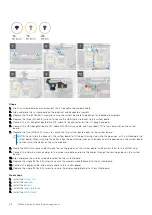
7. Replace the two (M1.6x4.5) screws to secure the two system board hooks to the system board.
NOTE:
Do not slide the hooks on the system board to fit the positioning studs into the openings, as this will damage the
system board. When installing the hooks, align the positioning studs on the hooks over the openings on the system board
and then install the hooks on the system board.
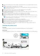
8. Route the WWAN antenna cable through the routing guides on the system board. and connect them to the WWAN card.
9. Connect the Darwin antenna cables to the wireless module, and route the cables through the routing guides on the system
board.
10. Align and place the wireless module bracket on the system board.
11. Replace the single (M1.6x4.5) screw to secure the wireless module bracket to the system board.
12. Connect the display cable, and camera cable to the system board.
13. Replace the single (M1.6x3.5) screw to secure the display-cable bracket to the system board.
Next steps
1. Install the
.
2. Install the
.
3. Install the
.
4. Install the
5. Install the
48
Removing and installing components

