3
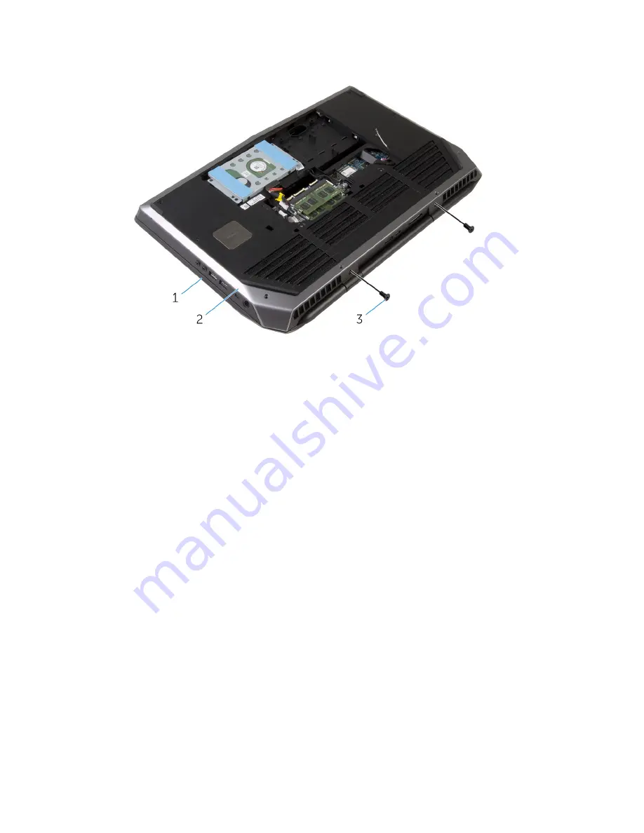
Remove the screws that secure the display assembly to the computer
base.
1
display assembly
2
computer base
3
screws (2)
4
Turn the computer over and open the display as far as possible.
5
Carefully remove the antenna cables through the slot on the computer
base.
6
Peel off the adhesive tape that secures the antenna cables to the system
board.
7
Remove the antenna cables from the routing guide on the display hinges.
8
Lift the latch and disconnect the display cable from the system board.
78
Summary of Contents for Alienware 15
Page 11: ...Getting help and contacting Alienware 149 Self help resources 149 Contacting Alienware 149 ...
Page 14: ... Philips screwdriver Plastic scribe 14 ...
Page 31: ...8 Disconnect the interposer from the hard drive 1 interposer 2 hard drive 31 ...
Page 47: ...5 Lift the touch pad off the palm rest assembly 1 palm rest assembly 2 touch pad 47 ...
Page 82: ...4 Replace the solid state drives 5 Replace the memory modules 6 Replace the base panel 82 ...
Page 86: ...5 Follow the procedure from step 1 to step 2 in Removing the logo board 1 display bezel 86 ...
Page 134: ...4 Lift the battery off the computer base 1 screws 2 2 battery 3 computer base 134 ...
Page 137: ...1 computer base 137 ...


