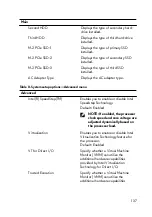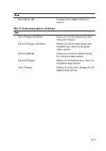
Advanced
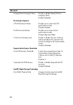
Always Perform Integrity Check
Enable or disable Always Perform
Integrity Check.
Default: Disabled
Performance Options
CPU Performance Mode
Enables you to select the CPU
performance mode.
Default: Enabled
Fan Performance Mode
Enables you to select the fan
performance mode.
Default: Balanced Mode
Core Over Clocking Level
Enable or disable the over-clocking
setting and adjust the processor flex
ratio and voltage in the Customization
mode.
Default: Disabled
SupportAssist System Resolution
Auto OS Recovery Threshold
Control the automatic boot flow for
SupportAssist System Resolution
Console and for Dell OS Recovery
tool.
Default: 2
SupportAssist OS Recovery
Enable or disable SupportAssist OS
recovery.
Default: Enabled
Intel(R) Rapid Storage Technology
Non-RAID Physical Disks
Displays the disk using the Intel(R)
Rapid Storage Technology.
140
Summary of Contents for Alienware 17 R5
Page 20: ...5 Replace the six screws M2 5x13 that secure the base cover to the computer base 20 ...
Page 23: ...7 Disconnect the interposer from the hard drive 23 ...
Page 26: ...7 Connect the hard drive cable to the system board Post requisites Replace the base cover 26 ...
Page 32: ...3 Slide and remove the solid state drive from the solid state drive slot 32 ...
Page 36: ...2 Slide and remove the memory module from the memory module slot 36 ...
Page 38: ...Post requisites Replace the base cover 38 ...
Page 40: ...3 Pull the rear I O cover from the computer base 40 ...
Page 42: ...Post requisites Replace the base cover 42 ...
Page 46: ...6 Lift the computer base off the palm rest assembly 46 ...
Page 51: ...5 Gently peel the coin cell battery along with its cable off the palm rest assembly 51 ...
Page 55: ...3 Lift the speakers along with its cable off the palm rest assembly 55 ...
Page 59: ...4 Turn the I O board over 5 Disconnect the subwoofer cable 59 ...
Page 60: ...6 Lift the I O board off the palm rest assembly 60 ...
Page 64: ...2 Lift the subwoofer along with its cable off the palm rest assembly 64 ...
Page 72: ...25 After performing all the above steps you are left with the system board 72 ...
Page 80: ...8 Lift the heat sink assembly off the system board 80 ...
Page 85: ...5 Remove the cable from the routing guides on the palm rest assembly 85 ...
Page 89: ...2 Lift the power button board along with its cable off the palm rest assembly 89 ...
Page 95: ...7 Lift the display assembly off the computer base 95 ...
Page 100: ...2 Lift the battery off the palm rest assembly 100 ...
Page 108: ...7 Replace the base cover 108 ...
Page 111: ...4 Peel off the macro keys cable and macro keys backlight cable from the keyboard 111 ...
Page 112: ...5 Lift the keyboard at an angle and remove it from the tabs on the palm rest assembly 112 ...
Page 116: ...13 Replace the base cover 116 ...
Page 122: ...Procedure After performing all the prerequisites we are left with the palm rest 122 ...
Page 124: ...19 Replace the base cover 124 ...

