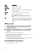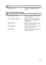
Keys
Navigation
Up arrow
Moves to the previous field.
Down arrow
Moves to the next field.
Enter
Selects a value in the selected field (if applicable) or follow
the link in the field.
Spacebar
Expands or collapses a drop
‐
down list, if applicable.
Tab
Moves to the next focus area.
NOTE: For the standard graphics browser only.
Esc
Moves to the previous page until you view the main screen.
Pressing Esc in the main screen displays a message that
prompts you to save any unsaved changes and restarts the
system.
BIOS overview
CAUTION: Unless you are an expert computer user, do not change the
settings in the BIOS Setup program. Certain changes can make your
computer work incorrectly.
NOTE: Before you change BIOS Setup program, it is recommended that
you write down the BIOS Setup program screen information for future
reference.
Use the BIOS Setup program for the following purposes:
•
Get information about the hardware installed in your computer, such as the
amount of RAM and the size of the hard drive.
•
Change the system configuration information.
•
Set or change a user-selectable option, such as the user password, type of hard
drive installed, and enabling or disabling base devices.
Entering BIOS setup program
1
Turn on (or restart) your computer.
134
Summary of Contents for Alienware 17 R5
Page 20: ...5 Replace the six screws M2 5x13 that secure the base cover to the computer base 20 ...
Page 23: ...7 Disconnect the interposer from the hard drive 23 ...
Page 26: ...7 Connect the hard drive cable to the system board Post requisites Replace the base cover 26 ...
Page 32: ...3 Slide and remove the solid state drive from the solid state drive slot 32 ...
Page 36: ...2 Slide and remove the memory module from the memory module slot 36 ...
Page 38: ...Post requisites Replace the base cover 38 ...
Page 40: ...3 Pull the rear I O cover from the computer base 40 ...
Page 42: ...Post requisites Replace the base cover 42 ...
Page 46: ...6 Lift the computer base off the palm rest assembly 46 ...
Page 51: ...5 Gently peel the coin cell battery along with its cable off the palm rest assembly 51 ...
Page 55: ...3 Lift the speakers along with its cable off the palm rest assembly 55 ...
Page 59: ...4 Turn the I O board over 5 Disconnect the subwoofer cable 59 ...
Page 60: ...6 Lift the I O board off the palm rest assembly 60 ...
Page 64: ...2 Lift the subwoofer along with its cable off the palm rest assembly 64 ...
Page 72: ...25 After performing all the above steps you are left with the system board 72 ...
Page 80: ...8 Lift the heat sink assembly off the system board 80 ...
Page 85: ...5 Remove the cable from the routing guides on the palm rest assembly 85 ...
Page 89: ...2 Lift the power button board along with its cable off the palm rest assembly 89 ...
Page 95: ...7 Lift the display assembly off the computer base 95 ...
Page 100: ...2 Lift the battery off the palm rest assembly 100 ...
Page 108: ...7 Replace the base cover 108 ...
Page 111: ...4 Peel off the macro keys cable and macro keys backlight cable from the keyboard 111 ...
Page 112: ...5 Lift the keyboard at an angle and remove it from the tabs on the palm rest assembly 112 ...
Page 116: ...13 Replace the base cover 116 ...
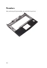
Page 122: ...Procedure After performing all the prerequisites we are left with the palm rest 122 ...
Page 124: ...19 Replace the base cover 124 ...

