background image

7

CHAPTER 1: SETTING UP YOUR DESKTOP 

CHAPTER 1: SETTING UP YOUR DESKTOP

CHAPTER 1: SETTING UP YOUR DESKTOP

Summary of Contents for Alienware Aurora R3

Page 1: ......

Page 2: ......

Page 3: ... ALIENWARE DESKTOP MANUAL ...

Page 4: ...Association Bluetooth is a registered trademark owned by Bluetooth SIG Inc and is used by Dell Inc under license Other trademarks and trade names may be used in this manual to refer to either the entities claiming the marks and names or their products Dell Inc disclaims any proprietary interest in trademarks and trade names other than its own Regulatory Model D0IM Regulatory Type D0IM003 Rev A00 S...

Page 5: ... Working With RAID 24 Optimizing Performance 26 Configuring the BIOS 26 CHAPTER 4 INSTALLING ADDITIONAL OR REPLACEMENT COMPONENTS 33 Before You Begin 34 Removing and Replacing the Side Panel 36 Inside View of Your Computer 37 Removing and Replacing Memory Module s 37 Removing and Replacing Hard Drive s 39 Removing and Replacing Expansion Card s 42 CHAPTER 5 TROUBLESHOOTING 45 Basic Hints and Tips ...

Page 6: ...4 ...

Page 7: ...ew computer meets or exceeds our very demanding criteria We have tested your computer extensively in order to ensure that you enjoy the highest levels of performance In addition to a standard burn in period your computer has been evaluated using real world tools such as synthetic performance benchmarks We invite you to share your experience with your new high performance computer with us so do not...

Page 8: ...6 ...

Page 9: ...7 CHAPTER 1 SETTING UP YOUR DESKTOP CHAPTER 1 SETTING UP YOUR DESKTOP CHAPTER 1 SETTING UP YOUR DESKTOP ...

Page 10: ...table The power and other cable connectors are not jammed between the desktop and a wall or any other object Nothing obstructs airflow in front of behind or below the desktop The desktop has enough room so that optical drives and other external storage drives can be easily accessed Before Setting Up Your Desktop Congratulations on the purchase of your Alienware Aurora Read all safety and setup ins...

Page 11: ...splayPort DisplayPort cable Connect the Display Connect the display using the connector available on the graphics card in the expansion card slot on your computer You can purchase the DVI to VGA adapter HDMI to DVI adapter and additional HDMI or DVI cables at www dell com Use the appropriate cable based on the connectors available on your computer and display See the following table to identify th...

Page 12: ...10 CHAPTER 1 SETTING UP YOUR DESKTOP Connect the Network Cable Optional Connect the Keyboard and Mouse ...

Page 13: ...ss the power button on the top of the computer Connect the Power Cable WARNING Thepowerconnectorsandpowerstripsvaryamongcountries Using an incompatible cable or improperly connecting the cable to a power strip or electrical outlet may cause fire or equipment damage ...

Page 14: ...rst time follow the instructions on the screen These steps are mandatory and may take some time to complete The Windows setup screens will take you through several procedures including accepting license agreements setting preferences and setting up an Internet connection CAUTION Do not interrupt the operating system s setup process Doing so may render your desktop unusable NOTE For optimal perform...

Page 15: ...rmation ready If you do not have an ISP the Connect to the Internet wizard can help you get one To set up your Internet connection Save and close any open files and exit any open programs 1 Click 2 Start Control Panel In the search box type 3 network and then click Network and Sharing Center Set up a new connection or network Connect to the Internet The Connect to the Internet window appears NOTE ...

Page 16: ...14 CHAPTER 1 SETTING UP YOUR DESKTOP ...

Page 17: ...YOUR DESKTOP This chapter provides information about your new desktop to familiarize you with its various features and to get you up and running quickly CHAPTER 2 GETTING TO KNOW YOUR DESKTOP CHAPTER 2 GETTING TO KNOW YOUR DESKTOP ...

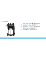
Page 18: ...DVDs and Blu ray Discs 3 Optical drive bay Can support additional optical drive 4 Media Card Reader Optical drive bay Can support an optional Media Card Reader or an additional optical drive 5 Drive panel Covers the optical drive s or optical drive bay s NOTE The drive panel is shown in the open position 6 Optical drive eject button Ejects the optical drive tray Front View Features 3 4 2 1 6 5 ...

Page 19: ...atch to the right to open the security cable slot and to unlock the release panel 3 Back panel connectors Connect USB audio and other devices into the appropriate connectors For more information see Back Panel Connectors on page 19 4 Expansion card slots Access connectors for any installed PCI and PCI Express cards 5 Power connector Connects to the power cable 6 Diagnostic light Indicates if the p...

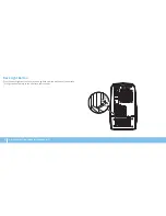
Page 20: ...18 CHAPTER 2 GETTING TO KNOW YOUR DESKTOP Back Light Button Press the back light button to turn on the light to view the back panel connectors This light automatically turns off after a few seconds ...

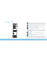
Page 21: ...rd printer external drive or MP3 player 4 USB 3 0 connector Provides faster data transmission between your computer and USB devices 5 Audio connectors Connect to speakers microphones and headphones NOTE For information on audio connectors see Connecting External Speakers on page 20 6 Network connector Connects your computer to a network or broadband device 7 IEEE 1394 connector Connects to high sp...

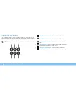
Page 22: ...nce NOTE On computers with a sound card use the connector on the card 1 2 3 5 6 4 1 Side L R surround connector Connects to side L R surround speakers 2 Rear L R surround connector Connects to rear L R surround speakers 3 Center subwoofer connector Connects to a center speaker or subwoofer 4 Line in connector Connects to recording or playback devices such as a microphone cassette player CD player ...

Page 23: ...21 CHAPTER 2 GETTING TO KNOW YOUR DESKTOP Top View Features Accessing the Top Panel Connectors Press the top panel downwards to access the top panel connectors 1 1 Top panel ...

Page 24: ... faster data transmission between your computer and USB devices 4 Power button Turns the computer on or off when pressed The color of the button rim indicates the power status Off the computer is either turned off in hibernate mode or is not receiving power Solid white the computer is on Blinking white the computer is in sleep or standby mode The color indicating the power status can be changed us...

Page 25: ...23 CHAPTER 3 USING YOUR DESKTOP CHAPTER 3 USING YOUR DESKTOP CHAPTER 4 USING YOUR DESKTOP ...

Page 26: ...s to your Alienware computer s power management controls to help increase energy efficiency Thermal Controls If you have vents present on top of your computer use thermal controls to control the thermal and venting capabilities of your computer by changing the fan speed and behavior of the vents Working With RAID A Redundant Array of Independent Disks RAID is a disk storage configuration that incr...

Page 27: ...rd drives combine to provide 4 GB of hard drive space on which to store data NOTE In a RAID 0 configuration the size of the configuration is equal to the size of the smallest drive multiplied by the number of drives in the configuration RAID Level 1 RAID level 1 uses data mirroring to enhance data integrity When data is written to the primary drive the data is also duplicated or mirrored on the se...

Page 28: ...stem components beyond the preset settings in the BIOS Doing so may cause system instability reduced component operating life or permanent component damage For computers with the Intel Core i7 Extreme Edition processor the BIOS has preset overclocking levels that allow you to easily overclock your computer For more information see Configuring the BIOS on page 26 Configuring the BIOS System Setup T...

Page 29: ...nt or changeable configuration information for your desktop Key functions appear at the bottom of the BIOS Setup Utility window and lists keys and their functions within the active field System Setup Options NOTE Depending on your computer and installed devices the items listed in this section may not appear or may not appear exactly as listed NOTE For the updated system setup information see the ...

Page 30: ... integrated in the computer SATA Port2 Displays the SATA 2 drive integrated in the computer Advanced Standard CMOS Features SATA Port3 Displays the SATA 3 drive integrated in the computer SATA Port4 Displays the SATA 4 drive integrated in the computer SATA Port5 Displays the SATA 5 drive integrated in the computer SATA Port6 Displays the SATA 6 drive integrated in the computer SATA Port7 Displays ...

Page 31: ...ard IEEE 1394 controller Onboard LAN Controller Allows you to enable or disable the onboard LAN controller LAN Option ROM Allows you to enable or disable the network controller s boot option Advanced Integrated Devices Jmicron 362 ATA Controller Allows you to enable or disable the ATA controller ICH SATA Configuration SATA Mode Allows you to configure the integrated hard drive controller to AHCI o...

Page 32: ...system End of Post Message Allows you to enable or disable the End of Post Message Advanced ME Subsystem Execute MEBx Allows you to enable or disable the Execute MEBx Integrated Clock Chip Configuration Allows you to access the Integrated Clock Chip Configuration submenu Advanced ME Subsystem Integrated Clock Chip Configuration Submenu ICC OverClocking Lib Version Displays the ICC OverClocking Lib...

Page 33: ... editable in Manual Mode tCKE Displays the Minimum CKE High and Low Pulse Width editable in Manual Mode Overclock Configuration Submenu Turbo Mode If enabled allows processor to run at faster frequencies than marked Long duration power limit Allows you to change the long duration power limit Long duration maintained Allows you to change the long duration time limit Short duration power limit Allow...

Page 34: ...d to enter the BIOS setup during POST Set Supervisor Password Allows you to set a supervisor password Boot Set Boot Priority 1st Boot Device Displays the first boot device 2nd Boot Device Displays the second boot device 3rd Boot Device Displays the third boot device 4th Boot Device Displays the fourth boot device 5th Boot Device Displays the fifth boot device 6th Boot Device Displays the sixth boo...

Page 35: ...u can purchase components for your desktop at www dell com or www alienware com NOTE See the Service Manual at support dell com manuals for installation instructions of all serviceable components Parts purchased from Dell and Alienware ship with specific replacement instructions CHAPTER 4 INSTALLING ADDITIONAL OR REPLACEMENT COMPONENTS CHAPTER 5 INSTALLING ADDITIONAL OR REPLACEMENT COMPONENTS ...

Page 36: ... order The procedures in this section may require the following tools Small flat blade screwdriver Phillips screwdriver BIOS executable update program available at support dell com Turning Off Your Desktop CAUTION To avoid losing data save and close all open files and exit all open programs before you turn off your desktop Save and close all open files and exit all open programs 1 Click 2 Start Sh...

Page 37: ...all telephone or network cables from the desktop 3 Disconnect your desktop and all attached devices from their electrical 4 outlets Press the power button to ground the system board 5 Before Working Inside Your Desktop Use the following safety guidelines to help protect your desktop from potential damage and to help to ensure your own personal safety WARNING Before working inside your desktop read...

Page 38: ...rity cable from the security cable slot if applicable Slide the latch to the right to unlock the release panel 2 Lift the release panel to open the side panel 3 Place the side panel in a secure location 4 NOTE Theater lighting turns on automatically when the side panel is removed Theater lighting is powered by internal batteries To replace the side panel push the side panel against the side of the...

Page 39: ...e memory module connectors on the system board see Inside 3 View of Your Computer on page 37 CAUTION The memory module s may become very hot during normal operation Allow the memory module s to cool before touching them NOTE For better access to memory module s remove the graphics card if the card is full length Spread apart the securing clips at both ends of the memory module 4 connector Lift the...

Page 40: ...memory module connector 4 3 2 1 1 memory module connector 2 tab 3 notch 4 memory module CAUTION To avoid damage to the memory module press the memory module straight down into the memory module connector while you apply equal force to each end of the memory module To replace memory module s Recommended memory configuration Type Slots 1333 MHz 1600 MHz and 1866 MHz Slots 1 and 2 or slots 1 4 ...

Page 41: ...erals to the computer 5 Turn on the computer 6 As the computer boots it detects the additional memory and automatically updates the system configuration information To confirm the amount of memory installed in the computer Click Start Control Panel System and Security System Removing and Replacing Hard Drive s NOTE For maximum performance of hard drive s connect the SATA 3 0 6Gb s compatible hard ...

Page 42: ...EPLACEMENT COMPONENTS 2 1 1 hard drive 2 release tabs 2 Remove the hard drive out of the hard drive bracket if applicable 5 2 1 1 power cable 2 data cable Press the release tabs together and slide the hard drive out of the hard 4 drive cage ...

Page 43: ...our computer Snap the new hard drive bracket on to the new hard drive if applicable 3 Slide the new hard drive into the hard drive cage until the release tabs snap 4 into place Connect the power and data cables if applicable 5 Replace the side panel see Removing and Replacing the Side Panel on 6 page 36 Reconnect the power cable and all the external peripherals to the computer 7 Turn on the comput...

Page 44: ...CI Express x16 card press the securing tab on the card connector as you grasp the card by its top corners and then ease the card out of the connector 2 3 1 1 PCI Express x16 card 2 securing tab 3 connector NOTE If you are not replacing a card install a filler bracket in the empty card slot opening Removing and Replacing Expansion Card s To remove a card Follow the instructions in Before You Begin ...

Page 45: ... on 8 page 36 Reconnect the power cable and all the external peripherals to the computer 9 Turn on the computer 10 To replace a card Follow the instructions in Before You Begin on page 1 34 Remove the filler bracket to create a card slot opening if applicable 2 Align the card with the slot on the connector 3 Place the card in the connector and press down firmly Ensure that the card 4 is firmly sea...

Page 46: ...44 CHAPTER 4 INSTALLING ADDITIONAL OR REPLACEMENT COMPONENTS ...

Page 47: ...45 CHAPTER 5 TROUBLESHOOTING CHAPTER 5 TROUBLESHOOTING CHAPTER 6 TROUBLESHOOTING ...

Page 48: ...program see the program s documentation Basic Hints and Tips The computer does not turn on Is your computer securely plugged into a working electrical outlet If plugged into a power strip ensure that the strip is working Connections Check all the cables to ensure that there are no loose connections anywhere Power Savings Ensure that your computer is not in hibernate or standby mode by pressing the...

Page 49: ...al tests for the system board keyboard display memory hard drive and so on To invoke PSA Turn on or restart your desktop 1 When the Alienware logo appears press F12 immediately to access the 2 Boot Menu NOTE Ifyouwaittoolongandtheoperatingsystemlogoappears continue to wait until you see the Microsoft Windows desktop then shut down your computer and try again Select 3 Diagnostics from the menu and ...

Page 50: ...iagnostics before you contact Alienware for technical assistance It is recommended that you print these procedures before you begin NOTE Back up all data before initiating a system recovery NOTE The Resource DVD contains drivers for your computer You can also download the latest drivers and software for your computer from support dell com Review your desktop s configuration information and ensure ...

Page 51: ...Seven Processor failure Computer Problems The computer fails the POST ThePowerOnSelfTest POST ensuresthatallhardwareisworkingproperlybefore starting the remainder of the boot process If the computer passes the POST the computer continues to start normally However if the computer fails the POST the computer emits a series of beeps during start up The following repetitive beep codes help you trouble...

Page 52: ...he computer stops responding or a solid blue screen appears CAUTION You might lose data if you are unable to perform an operating system shutdown If you are unable to get a response by pressing a key on your keyboard or moving your mouse press and hold the power button for at least 6 seconds until the computer turns off then restart your computer A program stops responding or crashes repeatedly En...

Page 53: ... protection your program may require an upgrade to scan the computer and remove spyware Check the software documentation or contact the software manufacturer for troubleshooting information Ensure that the program is compatible with the operating system installed on your computer Ensure that your computer meets the minimum hardware requirements needed to run the software For more information see t...

Page 54: ...ntinue Follow the instructions on the screen 4 Memory Memory errors detected on start up Check memory modules for correct seating and orientation Reseat the memory modules if applicable for more information see Removing and Replacing Memory Module s on page 37 Computers using a dual channel memory configuration require that memory modules be installed in pairs If you require assistance contact Ali...

Page 55: ...is properly connected to the surge protector or UPS When the computer is connected into an electric outlet press the diagnostic button and observe the diagnostic light to locate the diagnostic button and diagnostic light see Back View Features on page 17 If the diagnostic light turns ON the power supply is functioning as designed If the diagnostic light does not turn ON there may be a problem with...

Page 56: ...54 CHAPTER 5 TROUBLESHOOTING ...

Page 57: ...e Online is an online data backup service see Dell DataSafe Online Backup on page 57 System Drivers You can download the latest drivers for your computer from support dell com Resource DVD Contains drivers for your computer You can also download the latest system drivers from support dell com System Applications Some of the software that is pre installed on your computer does not include a backup ...

Page 58: ...lienRespawn Basic To restore the factory image while preserving the data files Turn off your computer 1 Disconnect all the devices connected to the computer such as USB drive 2 printer and so on and remove any recently added internal hardware NOTE Do not disconnect the monitor keyboard mouse and the power cable Turn on your computer 3 When the Alienware logo appears press F8 several times to acces...

Page 59: ...on your computer using a password protected account For more information go to delldatasafe com To schedule backups Double click the Dell DataSafe Online icon 1 on the taskbar Follow the instructions that appear on the screen 2 Upgrading to AlienRespawn Professional AlienRespawn provides additional features that allow you to Backup and restore your computer based on file types Backup files to a lo...

Page 60: ...58 CHAPTER 6 SYSTEM RECOVERY ...

Page 61: ...59 CHAPTER 7 SPECIFICATIONS This chapter provides specifications of your desktop CHAPTER 7 SPECIFICATIONS CHAPTER 8 SPECIFICATIONS ...

Page 62: ... desktop will vary depending on the configuration and the manufacturing variability Processor and System Chipset Processor Intel Core i7 Intel Core i5 Intel Core i3 L2 cache 256 KB L3 cache up to 8 MB System chipset Intel P67 DMI speed 2 5 GT s DRAM bus width 64 bits Processor address bus width 64 bits Data bus bandwidth up to 6 4 GT s RAID support internal SATA drives only RAID 0 RAID 1 RAID 1 0 ...

Page 63: ...nector Audio 7 1 channel line output stereo microphone and stereo line input connectors S PDIF one optical and one coaxial output connector Top Panel Connectors USB one 4 pin USB 3 0 compliant connector two 4 pin USB 2 0 compliant connectors Audio one stereo headphone and microphone connectors Communications Network adapter 10 100 1000 Ethernet LAN on system board Wireless optional WiFi Bluetooth ...

Page 64: ...city of 320 in s 813 cm s Altitude maximum Operating 15 2 to 3048 m 50 to 10 000 ft Storage 15 2 to 10 668 m 50 to 35 000 ft Airborne contaminant level G2 or lower as defined by ISA S71 04 1985 Expansion Bus PCI Express x1 Connectors two Connector size 36 pin connectors PCI Express x16 Connectors two Connector size 164 pins connectors Audio Type integrated 7 1 channel High Definition Audio with S ...

Page 65: ...d while replacing items inside the case especially if you are on a carpet or during low temperature and low humidity If you have to remove peripheral cards for any reason place them on the portion of the computer s case that was removed Do not touch the connectors at the bottom of the card that connect to the system board APPENDIX A GENERAL AND ELECTRICAL SAFETY PRECAUTIONS Computer Setup Read all...

Page 66: ... Your computer protects itself against most irregularities in the power source When Should You Contact Alienware The power cable or plug is damaged Your computer has had liquid spilled into it Your computer was dropped or the case was damaged Normal operation of the computer does not occur when the operating instructions are followed Replacement Components or Accessories It is only advised to use ...

Page 67: ...le Mexico APPENDIX B CONTACTING ALIENWARE For customers in the United States Canada call 1 800 ALIENWARE NOTE If you do not have an active Internet connection you can find contact information on your purchase invoice packing slip bill or Dell product catalog Dell provides several online and telephone based support and service options Because availability varies by country and product some services...

Page 68: ... of the Official Mexican Standard NOM Importer Dell México S A de C V Paseo de la Reforma 2620 Flat 11 Col Lomas Altas 11950 México D F Regulatory Model Number Regulatory Type Voltage Frequency Output Intensity D01M D01M003 100 240V AC 50 60 Hz 10 0 A 7 9 A For details read the safety information that shipped with your computer For additional safety best practices information see www dell com regu...

Page 69: ......

Page 70: ......

Reviews: