


Processor Liquid-Cooling Assembly
71
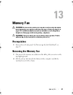
14
Processor Liquid-Cooling Assembly
WARNING:
Before working inside your computer, read the safety information
that shipped with your computer and follow the steps in "Before You Begin" on
page 13. For additional safety best practices information, see the Regulatory
Compliance Homepage at dell.com/regulatory_compliance.
Prerequisites
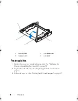
1
Remove the left side-panel. See "Removing the Left Side-Panel" on
page 25.
2
Open the PCI shroud. See "Opening the PCI Shroud" on page 45.
Removing the Processor Liquid-Cooling
Assembly
WARNING:
Despite having a plastic shield, the processor liquid-cooling
assembly may be very hot during normal operation. Ensure that it has had
sufficient time to cool before you touch it.
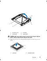
CAUTION:
To ensure maximum cooling for the processor, do not touch the heat
transfer areas on the processor liquid-cooling assembly. The oils in your skin can
reduce the heat transfer capability of the thermal grease.
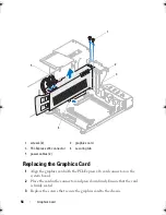
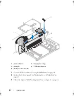
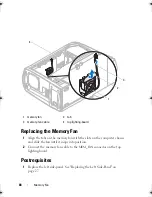
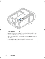
1
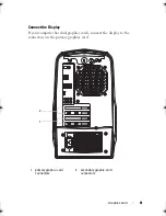
Press the tab on the CPU pump cable and disconnect the cable from the
top lighting-board.
2
Disconnect the system fan cable from the top lighting-board.
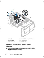
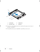
3
Loosen the captive screws that secure the processor liquid-cooling
assembly to the system board.
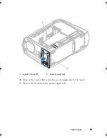
4
Remove the screws that secure the processor liquid-cooling assembly to
the chassis.
5
Slide and lift the processor liquid-cooling assembly out of the chassis.
book.book Page 71 Wednesday, May 16, 2012 2:37 PM
Summary of Contents for Alienware Aurora R4
Page 16: ...16 Before you Begin ...
Page 24: ...24 Technical Overview ...
Page 28: ...28 Left Side Panel ...
Page 31: ...Hard Drive s 31 2 Follow the steps in After Working Inside Your Computer on page 15 ...
Page 32: ...32 Hard Drive s ...
Page 36: ...36 Hard Drive Fan Assembly ...
Page 39: ...Optical Drive s 39 2 Follow the steps in After Working Inside Your Computer on page 15 ...
Page 40: ...40 Optical Drive s ...
Page 56: ...56 PCI Fan Assembly ...
Page 62: ...62 Graphics Card ...
Page 69: ...Memory Fan 69 2 Follow the steps in After Working Inside Your Computer on page 15 ...
Page 70: ...70 Memory Fan ...
Page 74: ...74 Processor Liquid Cooling Assembly ...
Page 81: ...Processor 81 ...
Page 82: ...82 Processor ...
Page 88: ...88 Power Supply ...
Page 92: ...92 Coin Cell Battery ...
Page 98: ...98 System Board Assembly ...
Page 102: ...102 Master I O Board ...
Page 106: ...106 Top Lighting Board ...
Page 108: ...108 Right Side Top Panel 2 Remove the screw that secures the right side top panel ...
Page 112: ...112 Right Side Top Panel ...
Page 116: ...116 Right Side Middle Panel ...
Page 120: ...120 Right Lighting Board ...
Page 135: ...Back Bezel 135 1 screws 2 2 back bezel 3 tabs 1 2 3 ...
Page 140: ...140 WiFi Bluetooth Assembly ...
Page 144: ...144 Top I O Panel ...
Page 158: ...158 System Setup Utility ...
Page 162: ...162 Specifications ...


