Steps
1
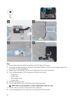
Ensure that the palm-rest assembly is placed face up with the keyboard facing you.
2 Gently place the display assembly on the palm-rest assembly and align the screw holes on the display assembly to the
screw holes on the palm-rest assembly.
3 Replace the six screws (M2.5x5) that secure the display assembly to the palm-rest assembly.
4 Route the following cables to the routing guides on the palm-rest assembly.
– Display cable
– G-sensor cable
– Tobii eye tracker cable
– Antenna cables
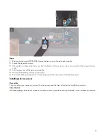
5 Place the computer face down.
6 Connect the Tobii eye tracker cable to the connector on the system board.
NOTE: This step is only applicable to computers shipped with a Tobii eye tracker.
7 Connect the G-sensor cable to the connector on the system board.
8 Connect the display cable to the connector on the system board and close the latch.
24
Summary of Contents for Alienware m15 R2
Page 1: ...Alienware m15 R2 Service Manual Regulatory Model P87F Regulatory Type P87F001 ...
Page 10: ...10 ...
Page 12: ...Steps 1 Connect the battery cable to the system board 12 ...
Page 40: ...40 ...
Page 43: ...43 ...
Page 56: ...56 ...

