Steps
1
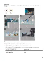
Using the alignment posts, adhere the keyboard-controller board into place on the palm-rest assembly.
2 Connect the keyboard-controller board-cable to the keyboard-controller board and close the connector latch.
3 Connect the keyboard cable to the keyboard-controller board and close the connector latch.
4 Connect the keyboard-backlight cable to the keyboard-controller board .
5 Replace the two screws (M2x1.9) that secure the keyboard-backlight cable to the keyboard-controller board.
Next steps
1
.
2
3
. (if applicable)
4
.
5
Follow the procedure in
After working inside your computer
Left I/O-board
Removing the left I/O-board
Prerequisite
1
Follow the procedure in
Before working inside your computer
.
2
Remove the
3
Remove the
. (if applicable)
4
Remove the
5
Remove the
About this task
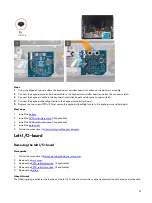
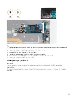
The following image indicates the location of the left I/O-board and provides a visual representation of the removal procedure.
31
Summary of Contents for Alienware m15 R2
Page 1: ...Alienware m15 R2 Service Manual Regulatory Model P87F Regulatory Type P87F001 ...
Page 10: ...10 ...
Page 12: ...Steps 1 Connect the battery cable to the system board 12 ...
Page 40: ...40 ...
Page 43: ...43 ...
Page 56: ...56 ...


