Steps
1
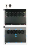
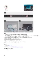
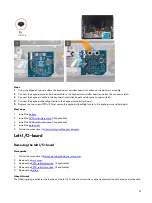
Push the rear I/O-cover into the palm-rest assembly snapping it into place.
NOTE: To avoiding damaging your computer, ensure the Tron light cable is not pinched and that the Mylar is
pasted on the system board before snapping the rear I/O-cover into place.
2 Replace the two screws (M2.5x5) that secure the rear I/O-cover to the palm-rest assembly.
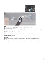
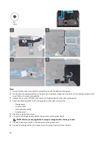
3 Peel and lift the Mylar from the system board.
4 Route the Tron light cable through the slot on the Mylar.
5 Connect the Tron light cable to the system board.
6 Route and adhere the Tron light cable into place on the system board.
7 Adhere the Mylar into place onto the system board.
Next steps
1
.
2
Follow the procedure in
After working inside your computer
Display assembly
20
Summary of Contents for Alienware m15 R2
Page 1: ...Alienware m15 R2 Service Manual Regulatory Model P87F Regulatory Type P87F001 ...
Page 10: ...10 ...
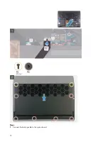
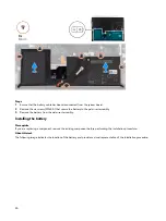
Page 12: ...Steps 1 Connect the battery cable to the system board 12 ...
Page 40: ...40 ...
Page 43: ...43 ...
Page 56: ...56 ...

