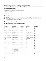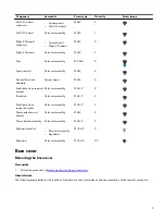
Component
Secured to
Screw type
Quantity
Screw image
Left I/O-board
connector
•
System board
•
Left I/O-board
M2x3
2
Left I/O-board
Palm-rest assembly
M2x3
1
Right I/O-board
connector
•
System board
•
Right I/O-board
M2x3
2
Right I/O-board
Palm-rest assembly
M2x3
2
Fans
Palm-rest assembly
M2.5x5
5
System board
Palm-rest assembly
M2x3
4
Fan and heat-sink
assembly
System board
M2x3
6
Solid-state drive support
bracket
Palm-rest assembly
M2x1.9
2
Touchpad
Palm-rest assembly
M2x1.9
4
Solid-state drive
support-bracket
Palm-rest assembly
M2x1.9
2
Power-adapter port
bracket
Palm-rest assembly
M2x3
2
Power-button assembly
Palm-rest assembly
M2x1.9
3
Keyboard bracket
•
Palm-rest assembly
•
Keyboard
M1.2x2.1
9
Keyboard
Palm-rest assembly
M1.2x1.6
33
Base cover
Removing the base cover
Prerequisite
1
Follow the procedure in
Before working inside your computer
.
About this task
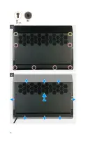
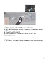
The following image indicates the location of the base cover and provides a visual representation of the removal procedure.
9
Summary of Contents for Alienware m15 R2
Page 1: ...Alienware m15 R2 Service Manual Regulatory Model P87F Regulatory Type P87F001 ...
Page 10: ...10 ...
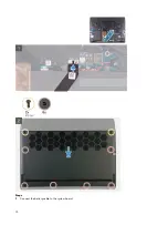
Page 12: ...Steps 1 Connect the battery cable to the system board 12 ...
Page 40: ...40 ...
Page 43: ...43 ...
Page 56: ...56 ...

