background image

12


About Your Monitor 

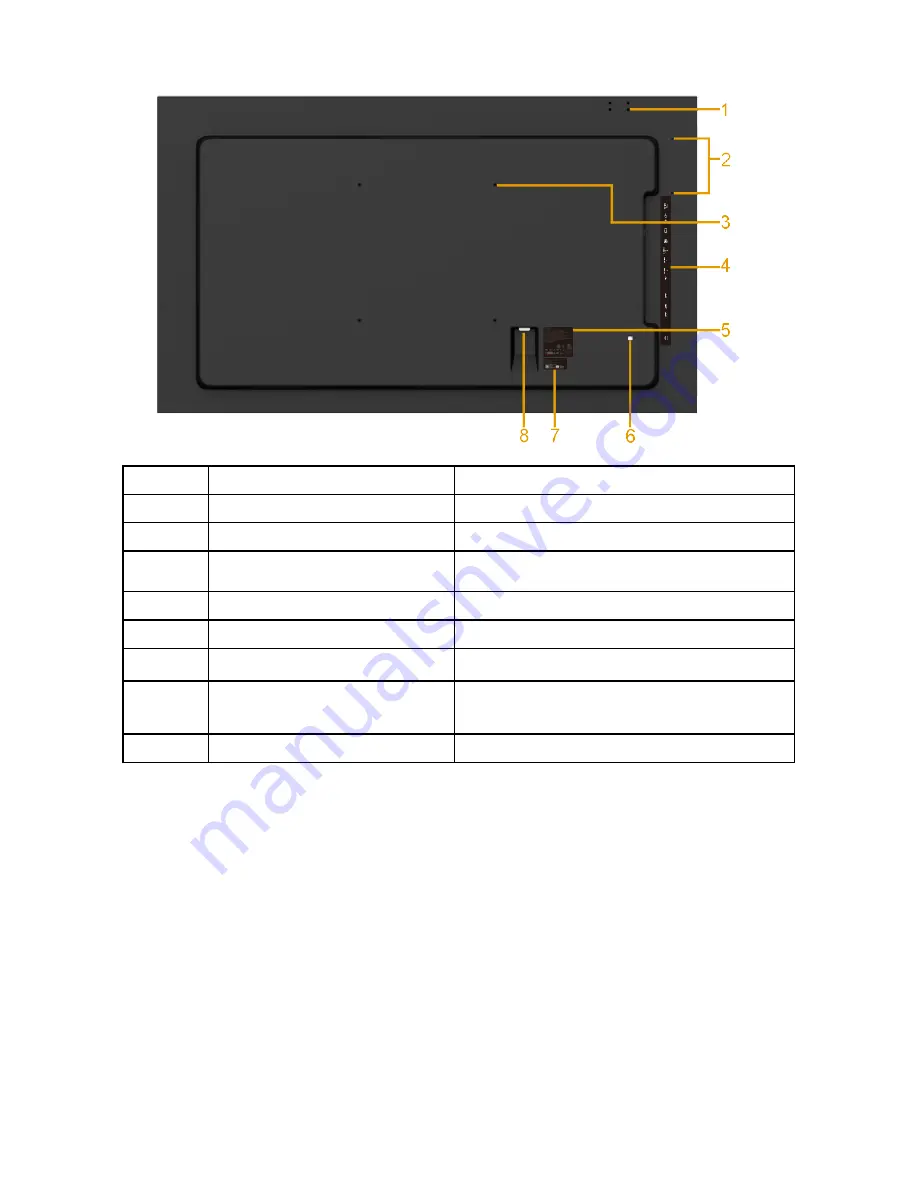
Back View

Label Description

Use

1

Screw Hole

For Accessory mounting.

2

Wire Saddle hole

For accessory wire saddle placement.

3

VESA mounting holes (400 
mm)

To mount the monitor.

4

RCA label

Indicates the connector type.

5

Regulatory rating label 

Lists the regulatory approvals.

6

RJ-45 connector

For remote control use.

7

Barcode serial number label  Refer to this label if you need to contact

Dell for technical support.

8

AC power connector

Connect the monitor power cable.

Summary of Contents for C7017T

Page 1: ...Regulatory model C7017Tf User s Guide Dell C7017T ...

Page 2: ...these materials in any manner whatsoever without the written permission of Dell Inc is strictly forbidden Trademarks used in this text Dell and the DELL logo are trademarks of Dell Inc Microsoft Windows and the Windows start button logo are either trademarks or registered trademarks of Microsoft Corporation in the United States and or other countries Other trademarks and trade names may be used in...

Page 3: ...lug and Play Capability 23 LCD Monitor Quality Pixel Policy 27 Maintenance Guidelines 28 Setting Up the Monitor 29 Connecting Your Monitor 29 Wall Mounting 32 Operating the Monitor 33 Power On the Monitor 33 Using the Front Panel Controls 33 Using the On Screen Display OSD Menu 34 Setting the Maximum Resolution 50 Dell Web Management for Monitors 52 ...

Page 4: ...0 Product Specific Problems 63 Universal Serial Bus USB Specific Problems 64 Mobile High Definition Link MHL Specific Problems 65 Touch Problems 65 Ethernet Problems 66 Appendix 67 Safety Instructions 67 FCC Notices U S Only and Other Regulatory Information 67 Contact Dell 67 ...

Page 5: ...elow Ensure that you have received all the components and Contact Dell if anything is missing NOTE Some items may be optional and may not ship with your monitor Some features or media may not be available in certain countries Monitor Remote Control Batteries AAA x 2 Remote control holder Stylus Stylus holder ...

Page 6: ...l Mount Kit Wire Saddle Power Cable varies with countries VGA Cable HDMI Cable DP Cable USB 3 0 upstream cable enables the USB ports on the monitor Drivers and Documentation media Quick Setup Guide Safety and Regulatory Information ...

Page 7: ...andards Association VESA 400 mm mounting holes Plug and play capability if supported by your system On Screen Display OSD adjustments for ease of set up and screen optimization Software and documentation media which includes an information file INF Image Color Matching File ICM and product documentation Dell Display Manager Software ENERGY STAR certificated Asset Management Capability CECP for Chi...

Page 8: ...the Volume 9 MUTE Press to turn the mute function on off 10 Preset Modes Display information about Preset Modes 11 Right Press to move the selection right in OSD menu 12 OK Confirm an entry or selection 13 Exit Press to exit the Menu 1 Power On Off Switch this monitor on or off 14 Brightness Press to increase the Brightness 2 Input Source Select input source Press or button to select from VGA or D...

Page 9: ...hese instructions Place AAA batteries matching the and signs on each battery to the and signs of the battery compartment Do not mix battery types Do not combine new batteries with used ones It causes shorter life or leakage of batteries Remove the dead batteries immediately to prevent them from liquid leaking in the battery compartment Don t touch exposed battery acid as it can damage your skin NO...

Page 10: ...e remote control within a distance of about 8 m from remote control sensor or at a horizontal and vertical angle of within 15 within a distance of about 5 6 m NOTE The remote control may not function properly when the remote control sensor on the display is under direct sunlight or strong illumination or when there is an obstacle in the path of signal transmission ...

Page 11: ...About Your Monitor 11 Identifying Parts and Controls Front View 1 IR Lens with LED indicator 2 Function buttons For more information see Operating the Monitor 3 Power On Off button with LED indicator ...

Page 12: ...nt 3 VESA mounting holes 400 mm To mount the monitor 4 RCA label Indicates the connector type 5 Regulatory rating label Lists the regulatory approvals 6 RJ 45 connector For remote control use 7 Barcode serial number label Refer to this label if you need to contact Dell for technical support 8 AC power connector Connect the monitor power cable ...

Page 13: ...ector Connect your computer with HDMI cable Connect your MHL devices with MHL cable 7 HDMI connector Connect your computer with HDMI cable 8 USB Down Stream Port Dedicated Charging Port Connect your USB devices for charging DCP port is for charging devices and has no data lines 9 USB Down Stream Port Connect your USB devices 10 USB upstream port Connect the USB cable that came with your monitor to...

Page 14: ...automatically resumes functioning The following table shows the power consumption and signaling of this automatic power saving feature VESA Modes Horizontal Sync Vertical Sync Video Power Indicator Power Consumption Normal operation Active Active Active White 230 W Maximum 145 W Typical Active off mode Inactive Inactive Blank Glowing white Less than 0 5 W Switch off Off Less than 0 3 W Network Sta...

Page 15: ...ting the main cable from the monitor Maximum power consumption with max luminance and contrast Energy consumption On Mode is tested at 230 Volts 50 Hz This document is informational only and reflects laboratory performance Your product may perform differently depending on the software components and peripherals you ordered and shall have no obligation to update such information Accordingly the cus...

Page 16: ...r Pin Number Monitor Side of the 9 pin Side Signal Cable 1 2 RX 3 TX 4 5 GND 6 7 Not Used 8 Not Used 9 VGA connector Pin Number Monitor Side of the 15 pin Side Signal Cable 1 Video Red 2 Video Green 3 Video Blue 4 GND 5 Self test 6 GND R 7 GND G 8 GND B ...

Page 17: ...ync 14 V sync 15 DDC clock DisplayPort Connector Pin Number 20 pin Side of the Connected Signal Cable 1 ML0 p 2 GND 3 ML0 n 4 ML1 p 5 GND 6 ML1 n 7 ML2 p 8 GND 9 ML2 n 10 ML3 p 11 GND 12 ML3 n 13 GND 14 GND 15 AUX p 16 GND 17 AUX n 18 HPD 19 DP_PWR_Return 20 3 3 V DP_PWR ...

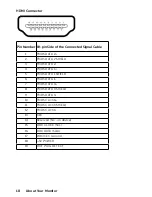
Page 18: ...TA 2 2 TMDS DATA 2 SHIELD 3 TMDS DATA 2 4 TMDS DATA 1 5 TMDS DATA 1 SHIELD 6 TMDS DATA 1 7 TMDS DATA 0 8 TMDS DATA 0 SHIELD 9 TMDS DATA 0 10 TMDS CLOCK 11 TMDS CLOCK SHIELD 12 TMDS CLOCK 13 CEC 14 Reserved N C on device 15 DDC CLOCK SCL 16 DDC DATA SDA 17 DDC CEC Ground 18 5V POWER 19 HOT PLUG DETECT ...

Page 19: ...ted Signal Cable 1 TMDS DATA 2 2 TMDS DATA 2 SHIELD 3 TMDS DATA 2 4 TMDS DATA 1 5 GND 6 TMDS DATA 1 7 MHL 8 TMDS DATA 0 SHIELD 9 MHL 10 TMDS CLOCK 11 GND 12 TMDS CLOCK 13 CEC 14 Reserved N C on device 15 DDC CLOCK SCL 16 DDC DATA SDA 17 GND 18 VBUS 5V 900mA maximum 19 CBUS ...

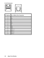
Page 20: ...20 About Your Monitor RJ 45 Connector Pin Number 12 pin Side of the Connector 1 D 2 RCT 3 D 4 D 5 RCT 6 D 7 GND 8 GND 9 LED2_Y 10 LED2_Y 11 LED1_G 12 LED1_G ...

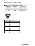
Page 21: ...he monitor NOTE This monitor is Super Speed USB 3 0 compatible Transfer Speed Data Rate Power Consumption Super Speed 5 Gbps 4 5W Max each port High Speed 480 Mbps 4 5W Max each port Full Speed 12 Mbps 4 5W Max each port USB Upstream Connector Pin Number 9 pin Side of the Connector 1 VCC 2 D 3 D 4 GND 5 SSTX 6 SSTX 7 GND 8 SSRX 9 SSRX ...

Page 22: ...eam 1 Dedicated Charging Port DCP DCP port is for charging devices and has no data lines NOTE USB 3 0 functionality requires a USB 3 0 capable computer NOTE The monitor s USB interface works only when the monitor is On or in the power save mode If you turn Off the monitor and then turn it On the attached peripherals may take a few seconds to resume normal functionality ...

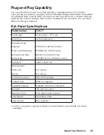
Page 23: ...17T Screen type Active matrix TFT LCD Panel Type Vertical Alignment Viewable image Diagonal 1765 63 mm 69 513 inches Horizontal Active Area 1538 88 mm 60 59 inches Vertical Active Area 865 62 mm 34 08 inches Active Area 1332085 31 mm2 2064 91 inches2 Pixel pitch 0 802 x 0 802 mm Viewing angle Horizontal 176 typical Vertical 176 typical Luminance output 380 cd m typical Contrast ratio 3800 to 1 typ...

Page 24: ...id Linux Mac OS iOS Glass Surface Anti Glare Anti Smudge Hardness 5H Glass Thickness 4 mm NOTE Windows XP Vista Mac OS are Single Touch Touch OS Compatibility OS Version Touch Points Windows XP Single Touch Vista 7 home basic 7 Ultimate Professional Home Premium Multi Touch 8 Pro Enterprise Non OEM version 8 0 8 1 Pro Enterprise Non OEM version 10 Home Professional Enterprise Educaiton Non OEM onl...

Page 25: ...ut signals Separate horizontal and vertical synchronizations polarity free TTL level SOG Composite SYNC on green AC input voltage frequency current 100 VAC to 240 VAC 50 Hz or 60 Hz 3 Hz 4 0 A Max Inrush current 120 V 40 A Max 240 V 80 A Max Preset Display Modes The following table lists the preset modes for which Dell guarantees image size and centering Display Mode Horizontal Frequency kHz Verti...

Page 26: ...p 50 1280 x 720p 60 1280 x 720p 50 1920 x 1080i 60 1920 x 1080i 50 1920 x 1080p 30 720 1440 x 480i 60 720 1440 x 576i 50 Physical Characteristics The following table lists the monitor s physical characteristics Model Number C7017T Connector type 15 pin D subminiature Black connector DP Black connector HDMI MHL Signal cable type VGA DisplayPort HDMI MHL Dimensions Height 932 61 mm 36 72 inches Widt...

Page 27: ...on operating 12 191 m 40 000 ft max Thermal dissipation 784 99 BTU hour maximum 495 89 BTU hour typical LCD Monitor Quality Pixel Policy During the LCD Monitor manufacturing process it is not uncommon for one or more pixels to become fixed in an unchanging state The visible result is a fixed pixel that appears as an extremely tiny dark or bright discolored spot When the pixel remains permanently l...

Page 28: ...or solution suitable for the antistatic coating Do not use benzene thinner ammonia abrasive cleaners or compressed air Use a slightly dampened warm cloth to clean the plastics Avoid using detergent of any kind as some detergents leave a milky film on the plastics If you notice a white powder when you unpack your monitor wipe it off with a cloth This white powder occurs during the shipping of the m...

Page 29: ...ny of the procedures in this section follow the Safety Instructions To connect your monitor to the computer 1 Turn off your computer and disconnect the power cable 2 Connect the VGA DP HDMI MHL cable to the corresponding video port on the back of your computer Connecting VGA Cable Connecting DP Cable ...

Page 30: ...30 Setting Up the Monitor Connecting HDMI cable Connecting MHL cable ...

Page 31: ... appropriate USB port on your computer See Side view for details 2 Connect the USB peripherals to the downstream USB ports on the monitor 3 Plug the power cables for your computer and monitor into a nearby outlet 4 Turn on the monitor and the computer If your monitor displays an image installation is complete If it does not display an image see Solving Problems NOTE The graphics are used for the p...

Page 32: ...it 400 x 400 mm distance 1 Install Wall Plate to Wall 2 Place the monitor panel on a soft cloth or cushion on a stable flat table 3 Attach the mounting brackets from the wall mounting kit to the monitor 4 Install Display to Wall Plate For more information see the Wall Mount provider website located at http www milestone com media Files Chief Manuals MSA1U_MTA1U_ LSA1U_LTA1U I pdf ...

Page 33: ...ption A Preset modes Use the Preset modes key to choose from a list of preset color modes See Using the OSD Menu B Volume Use the Volume key to direct access to the Volume control menu C Menu Use the Menu key to open the on screen display OSD D Exit Use the Exit key to exit on screen display OSD from menu and sub menus Front Panel Keys Front Panel Keys Description A Up Use the Up key to adjust inc...

Page 34: ...lay OSD Menu Accessing the Menu System NOTE If you change the settings and then either proceed to another menu or exit the OSD menu the monitor automatically saves those changes The changes are also saved if you change the settings and then wait for the OSD menu to disappear 1 Press the button to open the OSD menu and display the main menu Main Menu NOTE Auto Adjust is only available when you use ...

Page 35: ...elow provides a list of all the OSD menu options and their functions Icon Menu and Submenus Description Energy Use This meter shows the energy level being consumed by the monitor in real time Brightness Contrast Use the Brightness Contrast menu to adjust the Brightness Contrast Brightness Allows you to adjust the brightness or luminance of the backlight Press the key to increase brightness and pre...

Page 36: ...justment allows the monitor to self adjust to the incoming video signal After using Auto Adjustment you can further tune your monitor by using the Pixel Clock Coarse and Phase Fine controls under Display NOTE Auto Adjust does not occur if you press the button while there are no active video input signals or attached cables This option is only available when you are using the analog VGA connector ...

Page 37: ...ou are using the DP connector Push to select the DP input source HDMI1 MHL Select HDMI1 MHL input when you are using the HDMI1 MHL connector Push to select the HDMI1 MHL input source HDMI2 HDMI3 Select HDMI2 or HDMI3 input when you are using the HDMI2 or HDMI3 connector Push to select the HDMI2 or HDMI3 input source Auto Select Select Auto Select to scan for available input signals Reset Input Sou...

Page 38: ...the monitor s color settings Input Color Format Allows you to set the video input mode to RGB Select this option if your monitor is connected to a computer or DVD player using the DP adapter YPbPr Select this option if your DVD player supports only YPbPr output ...

Page 39: ...his is the default preset mode Warm Increases the color temperature The screen appears warmer with a red yellow tint Custom Color Allows you to manually adjust the color settings Press the and keys to adjust the Red Green and Blue values and create your own preset color mode Reset Color Resets your monitor s color settings to the factory defaults ...

Page 40: ... available for VGA input Sharpness This feature can make the image look sharper or softer Use or to adjust the sharpness from 0 to 100 Pixel Clock The Phase and Pixel Clock adjustments allow you to adjust your monitor to your preference Use or buttons to adjust for best image quality Phase If satisfactory results are not obtained using the Phase adjustment use the Pixel Clock coarse adjustment and...

Page 41: ...tons to adjust the volume Minimum is 0 Maximum is 100 Audio Source Allows you to set the Audio Source mode to PC Audio HDMI DP Speaker Allows you to enable or disable Speaker function Reset Audio Select this option to restore default display settings ...

Page 42: ...to save energy USB Allows you to enable or disable USB function during monitor standby mode NOTE USB ON OFF under standby mode is only available when USB upstream cable is unplugged This option will be greyed out when USB upstream cable is plugged in Reset Energy Select this option to restore default Energy settings ...

Page 43: ...OSD remains active after you press a key on the monitor Use the and keys to adjust the slider in 1 second increments from 5 to 60 seconds Lock Controls user access to adjustments When Lock is selected no user adjustments are allowed All keys are locked except key To unlock please use one of the following options 1 Press the menu key of remote control takes you directly to the OSD menu to unlock 2 ...

Page 44: ...e Monitor Personalize Selecting this option allows you to set two shortcut keys Shortcut Key 1 User can select from Preset Modes Brightness Contrast Auto Adjust Input Source Aspect Ratio Volume and set as shortcut key ...

Page 45: ... Shortcut Key 2 User can select from Preset Modes Brightness Contrast Auto Adjust Input Source Aspect Ratio Volume and set as shortcut key Reset Personaliza tion Allows you to restore shortcut key to the default setting Others ...

Page 46: ... of image retention If an image appears to be stuck on the monitor select LCD Conditioning to help eliminate any image retention Using the LCD Conditioning feature may take some time LCD Conditioning feature cannot remove severe cases of image retention or burn in NOTE Use LCD Conditioning only when you experience a problem with image retention The below warning message appears once user selects E...

Page 47: ...al that it is receiving from the computer See Monitor Specifications for the horizontal and vertical frequency ranges addressable by this monitor Recommended mode is 1920 x 1080 You will see the following message before the DDC CI function is disabled When the monitor enters the Power Save mode the following message appears Activate the computer and wake up the monitor to gain access to the OSD ...

Page 48: ...he power button the following messages will appear depending on the selected input If VGA DP HDMI1 MHL HDMI2 or HDMI3 cable is not connected a floating dialog box as shown below appears The monitor will enter Power Save Mode after 4 minutes if left at this state ...

Page 49: ...Operating the Monitor 49 See Solving Problems for more information ...

Page 50: ...lution 3 Click the dropdown list of the screen resolution and select 1920 x 1080 4 Click OK In Windows 10 1 Right click on the desktop and click Display settings 2 Click Advanced display settings 3 Click the dropdown list of Resolution and select 1920 x 1080 4 Click Apply If you do not see 1920 x 1080 as an option you may need to update your graphics driver Please choose the scenario below that be...

Page 51: ...ntroller supplier from the description at the top of the window e g NVIDIA ATI Intel etc 6 Please refer to the graphics card provider website for updated driver for example http www ATI com OR http www NVIDIA com 7 After installing the drivers for your graphics adapter attempt to set the resolution to 1920 x 1080 again In Windows 10 1 Right click on the desktop and click Display settings 2 Click A...

Page 52: ...eed to set the IP Addresses for your computer and the monitor 1 Press the Menu key on the remote control to display the IP Address of the monitor or by navigating to OSD Menu Others By default the IP Address is 10 0 50 100 2 In the computer s IP Properties tab specify an IP Address by selecting Use the following IP Address and enter the following values For IP Address 10 0 50 101 and for Subnet Ma...

Page 53: ... Monitor 53 3 The IP Address configuration would now look like this To access and use the web management tool follow these steps 1 Open a web browser and type the monitor s IP Address 10 0 50 100 in the address bar ...

Page 54: ...54 Operating the Monitor 2 The log in page opens Enter the Administrator Password to continue 3 The Home page opens ...

Page 55: ...Operating the Monitor 55 4 Click Network Settings tab to see the network settings ...

Page 56: ...56 Operating the Monitor 5 Click Monitor Control to see the monitor s status 6 Click Security to set a password ...

Page 57: ...Operating the Monitor 57 7 Update Firmware You can download the latest drivers from the Dell Support website at www dell com support ...

Page 58: ... back of computer 3 Turn on the monitor The floating dialog box should appear on screen against a black background if the monitor cannot sense a video signal and is working correctly While in self test mode the power LED remains white Also depending upon the selected input one of the dialogs shown below will continuously scroll through the screen 4 This box also appears during normal system operat...

Page 59: ...ideo cable s from the back of the computer or monitor The monitor then goes into the self test mode 3 Press and hold the Button 1 on the front panel for 5 seconds A gray screen appears 4 Carefully inspect the screen for abnormalities 5 Press the Button 1 on the front panel again The color of the screen changes to red 6 Inspect the display for any abnormalities 7 Repeat steps 5 and 6 to inspect the...

Page 60: ...rgy in OSD Menu No Video Power LED on No picture or no brightness Increase brightness contrast controls via OSD Perform monitor self test feature check Check for bent or broken pins in the video cable connector Ensure that the correct input source is selected via the Input Source Select menu Run the built in diagnostics Poor Focus Picture is fuzzy blurry or ghosting Perform Auto Adjust via OSD Adj...

Page 61: ...ural defect that can occur in LCD technology For more information on Dell Monitor Quality and Pixel Policy see Dell Support site at http www dell com support monitors Brightness Problems Picture too dim or too bright Reset the monitor to Factory Settings Auto Adjust via OSD Adjust brightness contrast controls via OSD Geometric Distortion Screen not centered correctly Reset the monitor to Factory S...

Page 62: ...o determine if the intermittent problem occurs in self test mode Missing Color Picture missing color Perform monitor self test feature check Ensure that the video cable connecting the monitor to the computer is connected properly and is secure Check for bent or broken pins in the video cable connector Wrong Color Picture color not good Change the Color Mode in the Color OSD to Graphics or Video de...

Page 63: ...information see Lock Or pressing the menu key of remote control takes you directly to the OSD settings menu with OSD Lock pre selected on entry use the and keys of remote control to select Unlock press of remote control to unlock for more information see Lock No Input Signal when user controls are pressed No picture the LED light is white When you press up down or Menu key the message No input sig...

Page 64: ...n the monitor again Re start the computer Some USB devices like external portable HDD require higher electric current connect the device directly to the computer system High Speed USB 3 0 interface is slow High Speed USB 3 0 peripherals working slowly or not working at all Check that your computer is USB 3 0 capable Some computers have both USB 3 0 and USB 2 0 and USB 1 1 ports Ensure that the cor...

Page 65: ...e connection is corresponding to input source selected on OSD Menu i e HDMI MHL Wait for 30 seconds after connecting MHL cable as some MHL devices require longer recovery time Touch Problems Common Symptoms What You Experience Possible Solutions No touchscreen response in saving mode Could not wake up monitor and computer by touching the screen in saving mode Ensure that the USB cable connecting t...

Page 66: ...nsure that the Network cable connecting the Monitor is properly secured Press and hold the Button 1 and Button 3 on the front panel for 3 seconds to turn on A network icon appears and is shown on Top left corner for 5 seconds Press and hold the Button 1 and Button 3 on the front panel for 3 seconds to turn off A network icon appears and is shown on Top left corner for 5 seconds ...

Page 67: ...ference that may cause undesired operation Contact Dell For customers in the United States call 800 WWW DELL 800 999 3355 NOTE If you do not have an active Internet connection you can find contact information on your purchase invoice packing slip bill or Dell product catalog Dell provides several online and telephone based support and service options Availability varies by country and product and ...

Reviews: