Table 2. Antenna-cable color scheme
Connectors on the
wireless card
Antenna-cable color
Silkscreen marking
Main
White
MAIN
△
(white triangle)
Auxiliary
Black
AUX
▲
(black triangle)
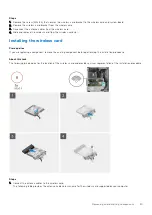
2. Align the notch on the wireless card with the tab on the wireless-card slot on the system board.
3. Slide and insert the wireless card at an angle into the wireless-card slot on the system board.
4. Adhere the wireless card to the adhesive pad.
5. Align the screw hole on the wireless-card bracket to the screw hole on the wireless card and system board.
6. Replace the screw (M2x3.5) that secures the wireless-card bracket to the wireless card and system board.
Next steps
1. Install the
.
After working inside your computer
.
Power supply unit
Removing the power-supply unit
Prerequisites
Before working inside your computer
.
2. Remove the
.
3. Remove the
.
NOTE:
Note the routing of all cables as you remove them so that you can route them correctly after you replace the
power-supply unit.
About this task
The following images indicate the location of the power-supply unit and provide a visual representation of the removal
procedure.
26
Removing and installing components


