background image

Replacing a fan

This procedure describes how to replace a fan.

Steps

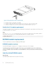
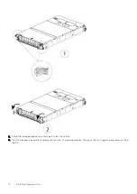
1. Press the fan locking tabs inward and hold them in this position.
2. With the locking tabs held inward, push the fan into its mounting location and release the locking tabs.

3. Slide the storage processor into the chassis as far as it will go (1).

Field Replaceable Units

13

Summary of Contents for DD6300

Page 1: ...Dell EMC Data Domain DD6300 DD6800 and DD9300 Field Replacement Unit Guide Part Number 302 003 009 August 2021 Rev 07 ...

Page 2: ...tial damage to hardware or loss of data and tells you how to avoid the problem WARNING A WARNING indicates a potential for property damage personal injury or death 2020 2020 Dell Inc or its subsidiaries All rights reserved Dell EMC and other trademarks are trademarks of Dell Inc or its subsidiaries Other trademarks may be trademarks of their respective owners ...

Page 3: ...ule replacement 18 NVRAM module replacement 18 NVRAM module overview 18 Identify a failed NVRAM module 18 Erase the NVRAM data 20 Remove the NVRAM module 21 Replacing the NVRAM module 22 Verify NVRAM 23 Power supply 24 Power supply overview 24 Identify the failed power supply unit 24 Remove a Power Supply 26 Replace a power supply 26 Verify the power supplies 27 DIMMs 27 DIMMs overview 27 Identify...

Page 4: ...g a failed disk drive 50 Removing a 3 5 disk drive 50 Installing a 3 5 disk drive 51 Verify the replacement 3 5 drive 52 DD6800 and DD9300 chassis 52 Preliminary and troubleshooting steps 53 Chassis replacement procedure 53 Verify the DD6800 or DD9300 system and perform a system headswap 54 DD6300 chassis 56 Preliminary and troubleshooting steps 56 Chassis replacement procedure 56 Verify the DD630...

Page 5: ...le 17 3 Inserting the I O module 17 4 Pushing the button on the I O module handle 18 5 CPU and memory locations 28 6 Sliding the 2 5 disk drive orange release button down 48 7 Removing a 3 5 disk drive 51 8 Installing a 3 5 disk drive 51 Figures Figures 5 ...

Page 6: ...operating maximum values to plan the configuration of your storage system These values represent either values for a single power supply line cord or the sum of the values shared by the line cords of the combined power supplies in the same enclosure with the division between the line cords and supplies at the current sharing ratio approximately 50 each A power and weight calculator is available at...

Page 7: ...el Optimus 15A fuse on the line side of each power supply both phases AC inlet type IEC320 C14 appliance coupler per power supply Ride through time 12 ms min Current sharing 5 of full load between power supplies Dimensions and weight Table 3 Dimensions and weight Dimensions Vertical size Weight see note Height 3 40 in 8 64 cm 2 NEMA units 80lbs 36 3 kg Width 17 50 in 44 45 cm Depth 30 5 in 77 5 cm...

Page 8: ...otocol types About this task For single node systems and HA pairs that have already failed over to the standby node skip these steps Steps 1 Enter the management IP address of the node containing the failed component into a web browser and login as sysadmin 2 Verify the node role and number in the upper right corner of the screen If the node is the standby node skip the next step 3 If the node is ...

Page 9: ...he six fans pull air into the system from the front of the enclosure past the disk drives through holes in the midplane and into the storage processor through the fans then across the CPU and other system board components through holes in the I O Risers then across the I O boards and power supplies then the air exits out the back of the system The six fans are located in the storage processor and ...

Page 10: ...y 17 22 15 34 2016 WARNING HardwareFailure Enclosure 1 Fan 4 Fan fault is detected There is 1 active alert 3 Use the enclosure show fans command to check the status of each fan Record the failed fan enclosure show fans 1 Enclosure Description Level Status 1 FAN 0A medium OK FAN 0B medium OK FAN 1A medium OK FAN 1B medium OK FAN 2A medium OK FAN 2B medium OK FAN 3A medium OK FAN 3B medium OK FAN 4A...

Page 11: ...ument FE Toolkit Inventory and Common Procedures for FRU Tasks at https support emc com 2 Label each of the cables as to their connection location Taking a photograph for reference is also helpful for re connecting the cables 3 Disconnect the power and data cables from the rear of the storage processor 4 On the storage processor extractors push up on the release buttons 1 and rotate the storage pr...

Page 12: ...torage processor and firmly pull it from the chassis 6 Press the locking tabs inward to release the fan from its mounting location Firmly pull the fan straight up and remove it from the SP 12 Field Replaceable Units ...

Page 13: ... 1 Press the fan locking tabs inward and hold them in this position 2 With the locking tabs held inward push the fan into its mounting location and release the locking tabs 3 Slide the storage processor into the chassis as far as it will go 1 Field Replaceable Units 13 ...
Page 14: ... show fans command to check the status of the enclosure fans enclosure show fans 1 Enclosure Description Level Status 1 FAN 0A medium OK FAN 0B medium OK FAN 1A medium OK FAN 1B medium OK FAN 2A medium OK FAN 2B medium OK FAN 3A medium OK FAN 3B medium OK FAN 4A medium OK FAN 4B medium OK FAN 5A medium OK FAN 5B medium OK Check the Status column to confirm that all of the fans in Enclosure 1 are O...

Page 15: ...ust have a filler panel installed in its empty slot The filler panel is plastic with a metal face plate and retains electromagnetic radiation inside the device This is required for EMI compliance and better airflow impedance for system cooling Table 4 I O module slots Model I O Module Slots DD6300 Default 0 and 1 2 is reserved All other I O slots optional DD6800 DD9300 Always populate 0 1 2 and 7 ...

Page 16: ... 02 18 83 4d 63 00 cc 7 PMC Quad Port 6 Gbps SAS 02 09 36 00 PMC_SAS2 7a 50 02 18 84 4d 61 00 cc 7b 50 02 18 84 4d 60 00 cc 7c 50 02 18 84 4d 62 00 cc 7d 50 02 18 84 4d 63 00 cc Removing an I O assembly This procedure describes how to remove an I O module About this task CAUTION I O modules are not hot pluggable or swappable Steps 1 Stop the system using the system poweroff command to allow the pr...

Page 17: ...cted surface Installing an I O module About this task To install an I O module Steps 1 Align the module with the empty slot and carefully push the module into the slot Figure 3 Inserting the I O module 2 When the I O module appears to be seated push and release the small button on the handle Field Replaceable Units 17 ...

Page 18: ...ke one to two minutes after the I O module replacement before the system clears the alert alerts show current No active alerts NVRAM module replacement This section describes how to remove and replace the NVRAM module NVRAM module overview The 8 GB NVRAM module is located in slot 0 It is removed in a fashion similar to the I O modules The NVRAM module provides 8GB of high speed NVRAM storage It us...

Page 19: ...del 3 1 Broadcom Quad Port 10GbE Base T 1a 1b 1c 1d 2 EMC PMC Quad Port 6 Gbps SAS 2a 2b 2c 2d 3 Broadcom Quad Port 10GbE SR 3a 3b 3c 3d 4 Broadcom Quad Port 10GbE SR 4a 4b 4c 4d 5 Broadcom Quad Port 10GbE SR 5a 5b 5c 5d 6 Broadcom Quad Port 10GbE SR 6a 6b 6c 6d 7 EMC PMC Quad Port 6 Gbps SAS 7a 7b 7c 7d 4 Enter the enclosure show nvram command to check information about the NVRAM enclosure show N...

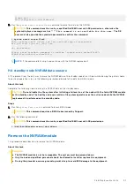
Page 20: ...rform the appropriate steps for the customer configuration Single node system NVRAM data erasure About this task Complete the following steps to erase the NVRAM data on a single node system Steps 1 Check the status of the file system and disable it if necessary CAUTION If the file system is not shut down you will not be able to erase the data from the NVRAM and you will get a message such as This ...

Page 21: ... the following workaround to delete the data from BASH mode About this task Complete the following steps to erase the NVRAM data on the standby node CAUTION Do not disable the file system after initiating a failover to set the node with the failed NVRAM module as the standby node The healthy node can continue file system operations as the active node while the NVRAM replacement is performed on the...

Page 22: ... CMA and the cabling out of the way to access the NVRAM module in slot 0 first slot on the left facing the cabinet from the rear 5 Grasp the handle trigger to release the NVRAM module 6 Pull on the handle to remove the NVRAM module from the chassis Replacing the NVRAM module This procedure describes how to replace the NVRAM module Steps 1 Align and slide the NVRAM module into slot 0 until it seats...

Page 23: ...ntroller Errors 0 Cfg Err 0 PANIC 0 Bus Hang 0 Bad Blk Warn 0 Bkup Err 0 Rstr Err Board temperature 39 C CPU temperature 48 C Number of batteries 1 NVRAM Batteries Card Battery Status Charge Charging Time To Temperature Voltage Status Full Charge 1 1 ok 95 enabled 0 mins 37 C 4 044 V 4 Enter the enclosure show misconfiguration command to verify if the NVRAM is in the correct slot enclosure show mi...

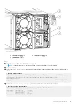
Page 24: ...restore the original active node Power supply This section describes how to remove and replace a power supply Power supply overview The node has two hot swappable 1050W power supply units that are accessible from the rear of the chassis When facing the rear of the unit the bottom power supply is unit 0 and the top is unit 1 Each power supply provides 1050 Watts of 12 Volt main power and 30 Watts o...

Page 25: ...sample output is shown alerts show current Id Post Time Severity Class Object Message 22 Tue May 3 18 46 56 2016 CRITICAL HWFailure Encl 1 PowerSupply 1 EVT ENVIRONMENT 00026 Power supply has failed 4 Enter the enclosure show powersupply command to check the status of each power supply enclosure show powersupply This command may take up to a minute to complete Please wait Enclosure Description Sta...

Page 26: ... as soon as possible CAUTION Whenever servicing parts in a running system move slowly while removing inserting or latching the new parts This avoids creating strong vibrations in the chassis which might interfere with other running parts Steps 1 Unlatch the bale securing the power supply power cord 2 Disconnect the power cord from the power supply 3 Press the orange unlocking tab to unlock the pow...

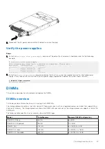
Page 27: ...ars the alert alerts show current No active alerts DIMMs This sections describes how to remove and replace the DIMMs DIMMs overview This topic provides information to assist servicing the DIMM FRUs The storage processor contains two Intel Haswell EP processors each with an integrated memory controller that supports four channels of memory The storage processor allows two DIMM slots per channel so ...

Page 28: ...hannel B Channel D Channel C Slot 0 1 2 3 4 5 6 7 DD6300 AIO Base 8GB 8GB 8GB Table 6 Memory locations CPU 1 Channel A Channel B Channel D Channel C Slot 8 9 10 11 12 13 14 15 DD6300 AIO Base 8GB 8GB 8GB DD6300 AIO Expanded 96 GB Table 7 Memory locations CPU 0 Channel A Channel B Channel D Channel C Slot 0 1 2 3 4 5 6 7 DD6300 AIO Expanded 8GB 8GB 8GB 8GB 8GB 8GB Table 8 Memory locations CPU 1 Cha...

Page 29: ...D9300 DLH Expanded 384 GB Table 13 Memory locations CPU 0 Channel A Channel B Channel D Channel C Slot 0 1 2 3 4 5 6 7 DD9300 DLH Expanded 32GB 16GB 32GB 16GB 16GB 32GB 16GB 32GB Table 14 Memory locations CPU 1 Channel A Channel B Channel D Channel C Slot 8 9 10 11 12 13 14 15 DD9300 DLH Expanded 32GB 16GB 32GB 16GB 16GB 32GB 16GB 32GB Identify failed DIMMs or failed memory riser Steps 1 Log in as...

Page 30: ...a DIMM memory module This procedure describes how to remove a DIMM About this task Steps 1 Stop the system using the system poweroff command to allow the proper shut down of the file system and other system components NOTE The system poweroff command completes when the front panel blue LED turns off For help connecting to a system using a laptop computer and terminal emulator see the document FE T...

Page 31: ...orage processor and firmly pull it from the chassis 4 Remove the air duct from the storage processor assembly 5 Press both tabs of the DIMM slot at the same time outwards to remove the DIMM Field Replaceable Units 31 ...

Page 32: ...he DIMM slot To install a DIMM Steps 1 Attach an ESD wristband to your wrist and the enclosure 2 Identify the slot from which the faulted DIMM was removed 3 Touching only the DIMM s outside edges align the module with the connector 4 Apply pressure to both top corners at the same time and firmly push the DIMM straight down into the connector 32 Field Replaceable Units ...

Page 33: ...ommand may take up to a minute to complete Please wait Enclosure 1 Number of DIMMS 12 Memory Size 98304 MiB Locator Speed Size Part No Serial No MHz MiB DIMM 0 2133 8192 18KSF1G72PDZ 1G6E1 DFBDA944 DIMM 2 2133 8192 18KSF1G72PDZ 1G6E1 32237E96 DIMM 4 2133 8192 18KSF1G72PDZ 1G6E1 DFBDA967 DIMM 5 2133 8192 18KSF1G72PDZ 1G6E1 32237E98 DIMM 6 2133 8192 18KSF1G72PDZ 1G6E1 32237D72 DIMM 7 2133 8192 18KSF...

Page 34: ... at https support emc com 2 Label each of the cables as to their connection location Taking a photograph for reference is also helpful for re connecting the cables 3 Disengage the wire clips then disconnect both AC power cords from the rear of the system 4 Label each of the cables as to their connection location Taking a photograph for reference is also helpful for re connecting the cables 5 Disco...

Page 35: ...a failed storage processor assembly to the replacement storage processor assembly About this task When the storage processor is replaced the internal components must be moved from the current processor to the replacement storage processor SP Steps 1 Remove the air duct from the current SP and the replacement SP Field Replaceable Units 35 ...

Page 36: ...the DIMMs one at a time from the current SP and install them in the same locations in the replacement SP 3 When the last DIMM has been moved replace the air duct in the replacement SP 36 Field Replaceable Units ...

Page 37: ...4 Move the fan modules from the current SP to the replacement SP 5 Move the power supply modules from the current SP to the replacement SP Field Replaceable Units 37 ...

Page 38: ...6 Remove the I O modules one at a time from the current SP and install them in the same locations in the replacement SP 38 Field Replaceable Units ...

Page 39: ...7 For DD6300 systems move the one or two rear mounted SSDs from the current SP to the replacement SP Field Replaceable Units 39 ...

Page 40: ...n levers upwards until the storage processor retracts fully into place and the storage processor extractors snap into place 2 NOTE The extractors snapping into place is not guaranteed Press the release buttons and then swing the extractors into place Then let go the release buttons If testing when the SP is fully seated attempt to swing out the extractors without releasing them 40 Field Replaceabl...

Page 41: ...rm that all of the fans in Enclosure 1 are OK 2 Enter the alerts show current command and confirm that the system has cleared the alert for the failed fan It may take one to two minutes after the fan replacement before the system clears the alert alerts show current No active alerts Verify the I O module replacement Check each I O module LED Each I O module ejector handle contains a bi colored LED...

Page 42: ...ntroller Errors 0 Cfg Err 0 PANIC 0 Bus Hang 0 Bad Blk Warn 0 Bkup Err 0 Rstr Err Board temperature 39 C CPU temperature 48 C Number of batteries 1 NVRAM Batteries Card Battery Status Charge Charging Time To Temperature Voltage Status Full Charge 1 1 ok 95 enabled 0 mins 37 C 4 044 V 4 Enter the enclosure show misconfiguration command to verify if the NVRAM is in the correct slot enclosure show mi...

Page 43: ...ersupply command The output for Enclosure 1 should be similar to the following example enclosure show powersupply This command may take up to a minute to complete Please wait Enclosure Description Status 1 Power module 0 OK 1 Power module 1 OK 2 Enter the alerts show current command and confirm that the system has cleared the alert for the failed power supply It may take one to two minutes after t...

Page 44: ...replacement drive is recognized by the Data Domain system In the command display the disk state should be spare or reconstructing disk show state Enclosure Disk 1 2 3 4 5 6 7 8 9 10 11 12 13 14 15 1 s R Legend State Count In Use Disks 6 s Spare Disks 1 R Spare reconstructing Disks 1 Total 8 disks Disk Disks Progress Remaining Group Reconstructing minutes dg0 1 14 4 15 2 A replacement drive that is...

Page 45: ...0 seconds KB article 497028 The Data Domain File System DDFS may be disabled if there is a backwards jump in system time configured on the system available from https support emc com provides more information a Run the ntp status command and note the NTP status time and date ntp status Status Enabled Current Clock Time Thu Feb 20 00 41 22 411 2020 Clock Last Synchronized Thu Feb 20 0 0 38 18 196 2...

Page 46: ...the software 2 5 Disk Drive Overview The rear of the enclosure supports up to two 2 5 SAS SSD drive carriers that slide into 2 5 drive bays The rear of the enclosure supports up to two 2 5 SAS SSD drive carriers that slide into 2 5 drive bays For AIO configurations these drive slots must use 1 SSD and the expanded configuration must use 2 SSDs For DLH configurations these slots are never populated...

Page 47: ...he system A steady amber LED light on a disk drive indicates that the disk has faulted Remove the 2 5 disk drive This procedure describes how to remove the 2 5 disk drive Steps 1 From the rear of the device press the release button down on the 2 5 disk drive cover to free it from the chassis 2 Remove the 2 5 disk drive cover Field Replaceable Units 47 ...

Page 48: ...se button downward to release it from its slot 1 The latch will rotate outward 2 Figure 6 Sliding the 2 5 disk drive orange release button down 4 Grasp the latch and pull the disk from its slot to remove it 48 Field Replaceable Units ...

Page 49: ... state command to display the state of all drives This command checks that the replacement drive is recognized by the Data Domain system In the command display the disk state should be spare or reconstructing disk show state Enclosure Disk 1 2 3 4 5 6 7 8 9 10 11 12 13 14 15 1 s R Legend State Count In Use Disks 6 s Spare Disks 1 R Spare reconstructing Disks 1 Total 8 disks Disk Disks Progress Rem...

Page 50: ...is task When a 3 5 drive fails the system service LED and the drive service LED will illuminate amber 1 System service LED 2 Drive activity service LED The following table shows the slot numbering of the front mounted disk drives Slot 0 Disk 1 Slot 1 Disk 2 Slot 2 Disk 3 Slot 3 Disk 4 Slot 4 Disk 5 Slot 5 Disk 6 Slot 6 Disk 7 Slot 7 Disk 8 Slot 8 Disk 9 Slot 9 Disk 10 Slot 10 Disk 11 Slot 11 Disk ...

Page 51: ...n ESD wristband to your wrist and the enclosure in which you are installing the disk 2 Insert the disk in the slot as follows a With the disk s latch fully open gently push the disk into the slot 1 The latch begins to rotate to the right when its tabs meet the enclosure b Push the handle inward to engage the latch 2 Figure 8 Installing a 3 5 disk drive Results The disk s active light flashes to re...

Page 52: ...ks 2 If the disk drive shows as failed or unknown enter the following command with the correct disk id disk unfail 1 6 The disk unfail command will add the disk to the head unit and mark it as a spare Any existing data on this disk will be lost Are you sure yes no no yes ok proceeding 3 Generate an autosupport when the disk drive replacement is completed Issue the following command from the comman...

Page 53: ... chassis replacement During the procedure wear a grounding wrist strap to avoid ESD damage to the equipment Data Domain recommends putting the current chassis and the new chassis on an ESD free work surface that is large enough for the new and old systems to be side by side on a table or counter top to ensure the correct placement of all components in the new chassis CAUTION If it is necessary to ...

Page 54: ...he current chassis b Pull out on the tag Some force may be needed to remove the tag c Insert the tag into the new chassis 8 Install the chassis into the cabinet as follows a From the front of the cabinet align the rear of the chassis with the lip of each installed rail b Carefully slide the chassis all the way into the cabinet c Attach the chassis to the cabinet using two screws 9 If applicable in...

Page 55: ... CIFS domain by issuing the command cifs set authentication active directory domainname b For systems with the Replication feature Use the replication modify commands to update the hostname 8 If needed verify the functionality of the I O modules For specific information refer to the Data Domain DD6300 DD6800 and DD9300 Field Replacement Unit Guide 9 NOTE The user information is retained in the man...

Page 56: ...e disk show hardware system show ports disk multipath status filesys show space enclosure show topology vtl show config vtl group show all enclosure show power supply NOTE When you run these commands before and after the chassis replacement the output should be the same Save this information in case any configuration problems are found after the procedure has completed See the Data Domain Operatin...

Page 57: ...tem using the system poweroff command for example if the system becomes unresponsive Steps 1 Locate the recessed power button on the back of the management panel indicated by two facing triangles 2 Using a ballpoint pen or the end of a paperclip press and hold the button for ten seconds Chassis replacement This procedure describes how to replace a chassis Steps 1 Remove the CMA if applicable 2 Rem...

Page 58: ...te The correct disks are seen The data storage is not configured The data storage is foreign storage and that there is a complete set of foreign storage available 5 Verify the health of the file system by entering these two commands filesys status NOTE If the output of this command shows that the filesystem is down attempt to enable the filesystem using the filesys enable command before entering t...

Page 59: ...s captured in Preliminary and troubleshooting steps on page 53 to confirm FC I O configuration Refer also to the Data Domain System Controller Upgrade Guide for more information Bring HA back online About this task For HA systems bring the HA configuration back online Steps 1 Run the ha online command on the standby node to bring the HA configuration back online 2 For HA systems that were failed o...

Page 60: ...rail mounting holes of 7 1 MM diameter round or M5 12 24 10 32 threaded are being used install the filler using the pin as shown If not proceed to the next step Once the filler is installed to the rail the installation can continue as follows 2 At the front of the cabinet insert the two adaptors on the front of the rail into the correct holes in the 2U space 3 60 Installation and Removal of the Ra...

Page 61: ...with the mounting holes in the NEMA channel Make sure the rail is level 5 Use an 18 inch screwdriver minimum to secure the rear of the rail to the NEMA channel using one screw 6 Tighten the front screw 7 Repeat for the other rail Install onto the rails This procedure describes how to install the instrument onto the rails Steps 1 Slide the unit onto the rails and push it fully into the cabinet unti...

Page 62: ...ing four screws two on each side Remove from the rails This procedure describes how to remove the instrument from the rails Steps 1 Remove the four screws securing the unit to the NEMA channel and to the rail 62 Installation and Removal of the Rail Kit ...

Page 63: ...2 Pull the unit out of the rails and out of the cabinet CAUTION System may weigh up to 80 lbs Make sure two persons are dismounting the system from the rack Installation and Removal of the Rail Kit 63 ...

Reviews: