background image

18

Setting Up and Using Your Computer

If you do not have an 

MSN Explorer

 or 

AOL

 icon on your desktop or if you want to set up an 

Internet connection with a different ISP:

1

Save and close any open files, and exit any open programs.

2

Click the 

Start

 button and click 

Internet Explorer

.

The 

New Connection Wizard 

appears.

3

Click 

Connect to the Internet

.

4

In the next window, click the appropriate option:

If you do not have an ISP and want to select one, click 

Choose from a list of Internet 

service providers (ISPs)

.

If you have already obtained setup information from your ISP but you did not receive a 
setup CD, click 

Set up my connection manually

.

If you have a CD, click 

Use the CD I got from an ISP

.

5

Click 

Next

.

If you selected 

Set up my connection manually

, continue to step 6. Otherwise, follow the 

instructions on the screen to complete the setup.


NOTE: 

If you do not know which type of connection to select, contact your ISP.

6

Click the appropriate option under 

How do you want to connect to the Internet?

, and then 

click 

Next

.

7

Use the setup information provided by your ISP to complete the setup.

If you are having problems connecting to the Internet, see "E-Mail, Modem, and Internet 
Problems" on page 31. If you cannot connect to the Internet but have successfully connected in the 
past, the ISP might have a service outage. Contact your ISP to check the service status, or try 
connecting again later.
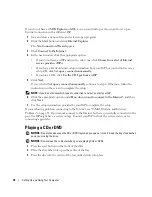
Playing a CD or DVD


NOTICE: 

Do not press down on the CD or DVD tray when you open or close it. Keep the tray closed when 

you are not using the drive.


NOTICE: 

Do not move the computer when you are playing CDs or DVDs.
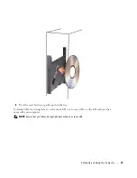
1

Press the eject button on the front of the drive.

2

Place the disc, label side up in the center of the tray 

3

Press the disc into the center of the tray until it clicks into place.

Summary of Contents for Dimension 5150C

Page 1: ...nal floppy drive or Media Card Reader network connector IEEE 1394 connector voltage selection switch USB 2 0 connectors 5 center LFE connector modem connector CD or DVD drive light USB 2 0 connectors 2 IEEE 1394 connector power connector integrated video connector S PDIF out connector microphone side surround sound connector PCI Express x16 card slot PCI Express x1 card slot line out connector lin...

Page 2: ... Inc All rights reserved Reproduction in any manner whatsoever without the written permission of Dell Inc is strictly forbidden Trademarks used in this text Dell the DELL logo Inspiron DellPrecision Dimension OptiPlex Latitude PowerEdge PowerVault PowerApp DellNet and PowerConnect are trademarks of Dell Inc Intel Pentium Intel SpeedStep and Celeron are registered trademarks of Intel Corporation Mi...

Page 3: ...Up a Home and Office Network 16 Connecting to a Network Adapter 16 Network Setup Wizard 17 Connecting to the Internet 17 Setting Up Your Internet Connection 17 Playing a CD or DVD 18 Adjusting the Volume 21 Adjusting the Picture 21 Copying CDs and DVDs 21 How to Copy a CD or DVD 21 Using Blank CDs and DVDs 22 Helpful Tips 23 Power Management 24 Standby Mode 24 Hibernate Mode 24 Power Options Prope...

Page 4: ...m and Internet Problems 31 Error Messages 32 Media Card Reader Problems 33 IEEE 1394 Device Problems 33 Keyboard Problems 34 Lockups and Software Problems 34 The computer does not start up 34 The computer stops responding 35 A program stops responding 35 A program crashes repeatedly 35 A program is designed for an earlier Windows operating system 35 A solid blue screen appears 35 Other software pr...

Page 5: ...stics Main Menu 48 Drivers 49 What Is a Driver 49 Reinstalling Drivers 50 Resolving Software and Hardware Incompatibilities 51 Restoring Your Operating System 51 Using Microsoft Windows XP System Restore 51 4 Removing and Installing Parts Before You Begin 55 Recommended Tools 55 Turning Off Your Computer 55 Before Working Inside Your Computer 55 Front and Back View of the Computer 57 Front View 57...

Page 6: ...Drive Cables 74 Hard Drive 75 Removing a Hard Drive 76 Installing a Hard Drive 77 CD DVD Drive 78 Removing a CD DVD Drive 78 Installing a CD DVD Drive 80 Media Card Reader 81 Removing a Media Card Reader 82 Installing a Media Card Reader 83 Floppy Drive Optional 85 Removing a Floppy Drive 85 Installing a Floppy Drive 87 Modem 89 Replacing the Modem 89 Replacing the External Modem Connector 90 Batt...

Page 7: ... Passwords 107 Clearing CMOS Settings 108 Cleaning Your Computer 108 Computer Keyboard and Monitor 108 Mouse 109 CDs and DVDs 109 Dell Technical Support Policy U S Only 110 Definition of Dell Installed Software and Peripherals 110 Definition of Third Party Software and Peripherals 110 FCC Notices U S Only 110 FCC Class B 110 Contacting Dell 111 Index 129 ...

Page 8: ...8 Contents ...

Page 9: ...ountries NOTE Additional information may ship with your computer What Are You Looking For Find it Here Warranty information Terms and Conditions U S only Safety instructions Regulatory information Ergonomics information End User License Agreement Dell Product Information Guide How to set up my computer Setup Diagram ...

Page 10: ...online discussions with technical support Reference Computer documentation details on my computer configuration product specifications and white papers Downloads Certified drivers patches and software updates Desktop System Software DSS If you reinstall the operating system for your computer you should also reinstall the DSS utility DSS provides critical updates for your operating system and suppo...

Page 11: ... such as a modem Windows Help and Support Center 1 Click the Start button and click Help and Support 2 Type a word or phrase that describes your problem and click the arrow icon 3 Click the topic that describes your problem 4 Follow the instructions on the screen What Are You Looking For Find it Here ...

Page 12: ...12 Finding Information ...

Page 13: ...tall updated drivers Connect the printer to the computer Load paper and install the toner or ink cartridge Contact the printer manufacturer for technical assistance Printer Cable Your printer connects to your computer with a USB cable Your printer may not come with a printer cable so if you purchase a cable separately ensure that it is compatible with your printer If you purchased a printer cable ...

Page 14: ...ttach the USB printer cable to the USB connectors on the computer and the printer The USB connectors fit only one way Using a Media Card Reader Optional Use the Media Card Reader to transfer data directly to your computer The Media Card Reader supports the following memory types xD Picture Card SmartMedia SMC CompactFlash Type I and II CF I II MicroDrive Card SecureDigital Card SD MultiMediaCard M...

Page 15: ...in Connecting a TV Optional NOTE To connect a TV to your computer you must have a video card that has TV out functionality and an S video cable which is available at most consumer electronics stores An S video cable is not included with your computer 1 Follow the procedures in Before You Begin on page 55 2 Connect one end of the S video cable to the TV OUT connector on the back of the computer 3 C...

Page 16: ... the Start button click Help and Support click User and system guides click Device guides and then click the guide for your graphics card Setting Up a Home and Office Network Connecting to a Network Adapter NOTE Plug the network cable into the network adapter connector on the computer Do not plug the network cable into the modem connector on the computer Do not plug a network cable into a telephon...

Page 17: ... Internet service provider ISP such as AOL or MSN Your ISP will offer one or more of the following Internet connection options Dial up connections that provide Internet access through a telephone line Dial up connections are considerably slower than DSL and cable modem connections DSL connections that provide high speed Internet access through your existing telephone line With a DSL connection you...

Page 18: ...the instructions on the screen to complete the setup NOTE If you do not know which type of connection to select contact your ISP 6 Click the appropriate option under How do you want to connect to the Internet and then click Next 7 Use the setup information provided by your ISP to complete the setup If you are having problems connecting to the Internet see E Mail Modem and Internet Problems on page...

Page 19: ...19 4 Press the eject button or gently push in the tray To format CDs for storing data to create music CDs or to copy CDs see the CD software that came with your computer NOTE Ensure that you follow all copyright laws when you create CDs ...

Page 20: ...more information on playing CDs or DVDs click Help on the CD or DVD player if available Play Move backward within the current track Pause Move forward within the current track Stop Go to the previous track Eject Go to the next track Stop Play Fast forward Pause Fast reverse Go to the next title or chapter Go to the previous title or chapter ...

Page 21: ... by 600 pixels 5 Click the drop down menu under Color quality and then click Medium 16 bit 6 Click OK Copying CDs and DVDs NOTE Ensure that you observe all copyright laws when creating CDs or DVDs This section applies only to computers that have a CD RW DVD RW or CD RW DVD combo drive NOTE The types of CD or DVD drives offered by Dell may vary by country The following instructions explain how to m...

Page 22: ...copying the source CD or DVD the CD or DVD that you have created automatically ejects Using Blank CDs and DVDs CD RW drives can write to CD recording media only including high speed CD RW while DVD writable drives can write to both CD and DVD recording media Use blank CD Rs to record music or permanently store data files After creating a CD R you cannot write to that CD R again see the Sonic docum...

Page 23: ...by your DVD player see the documentation provided with your DVD player or contact the manufacturer Do not burn a blank CD R or CD RW to its maximum capacity for example do not copy a 650 MB file to a blank 650 MB CD The CD RW drive needs 1 2 MB of the blank space to finalize the recording Use a blank CD RW to practice CD recording until you are familiar with CD recording techniques If you make a m...

Page 24: ...lick Control Panel 2 Under Pick a category click Performance and Maintenance 3 Under or pick a Control Panel icon click Power Options To immediately activate standby mode without a period of inactivity click the Start button click Turn Off Computer and then click Stand by To exit from standby mode press a key on the keyboard or move the mouse NOTICE If your computer loses power while in standby mo...

Page 25: ...ate mode turning off the monitor and turning off the hard drive The Power schemes drop down menu displays the following schemes Always On default If you want to use your computer with no power conservation Home Office Desk If you use your computer as a home or office computer and you require minimal power conservation Portable Laptop If your computer is a portable computer that you use for traveli...

Page 26: ...omputer Understanding Intel Viiv Technology Optional Intel Viiv technology is a technology aimed at the digital home enthusiast that includes A BIOS with Quick Resume Device drivers This technology allows the user s system to quickly return to an active state after non use Intel Viiv technology is an option for systems that are ordered with Microsoft Windows XP Media Center Edition 2005 and dual c...

Page 27: ...trol Panel icon click Power Options 4 Click the Away tab 5 Ensure that the check boxes for Enable away mode and Options are checked 6 Click the Advanced tab 7 From the When I press the power button on my computer drop down menu select Do Nothing 8 From the When I press the sleep button on my computer drop down menu select Do Nothing Hyper Threading Hyper Threading is an Intel technology that can e...

Page 28: ...lick My Computer and then click Properties 2 Click Hardware and click Device Manager 3 In the Device Manager window click the plus sign next to Processors If Hyper Threading is enabled the processor is listed twice You can enable or disable Hyper Threading through system setup For more information on accessing system setup see page 100 ...

Page 29: ...ed by the manufacturer Discard used batteries according to the manufacturer s instructions CAUTION Before you begin any of the procedures in this section follow the safety instructions located in the Product Information Guide Drive Problems CAUTION Before you begin any of the procedures in this section follow the safety instructions located in the Product Information Guide REPLACE THE BATTERY If y...

Page 30: ...CK THE CABLE CONNECTIONS RUN THE HARDWARE TROUBLESHOOTER See page 51 RUN THE DELL DIAGNOSTICS See page 48 ADJUST THE WINDOWS VOLUME CONTROL Click the speaker icon in the lower right corner of your screen Ensure that the volume is turned up by clicking the slidebar and dragging it up Ensure that the sound is not muted by clicking any boxes that are checked CHECK THE SPEAKERS AND SUBWOOFER See Sound...

Page 31: ...K THE TELEPHONE LINE CONNECTION CHECK THE TELEPHONE JACK CONNECT THE MODEM DIRECTLY TO THE TELEPHONE WALL JACK USE A DIFFERENT TELEPHONE LINE Verify that the telephone line is connected to the jack on the modem The jack has either a green label or a connector shaped icon next to it Ensure that you hear or feel a click when you insert the telephone line connector into the modem Disconnect the telep...

Page 32: ...nsure that you have subscribed to an Internet provider With the Outlook Express e mail program open click File If Work Offline has a checkmark next to it click the checkmark to remove it and connect to the Internet For help contact your Internet service provider A FILENAME CANNOT CONTAIN ANY OF THE FOLLOWING CHARACTERS Do not use these characters in filenames A REQUIRED DLL FILE WAS NOT FOUND The ...

Page 33: ...Reader the device is automatically assigned a drive letter as the next logical drive after all other physical drives in the system If the next logical drive after the physical drives is mapped to a network drive Windows XP does not automatically assign a drive letter to the Media Card Reader To manually assign a drive for the Media Card Reader 1 Right click My Computer and select Manage 2 Select t...

Page 34: ...he device IF YOU HAVE PROBLEMS WITH A DELL IEEE 1394 DEVICE Contact Dell see page 111 IF YOU HAVE PROBLEMS WITH A NON DELL IEEE 1394 DEVICE Contact the manufacturer of the IEEE 1394 device CHECK THE KEYBOARD CABLE Ensure that the keyboard cable is firmly connected to the computer Reconnect the keyboard cable as shown on the setup diagram for your computer Check the cable connector for damaged or f...

Page 35: ...END THE PROGRAM 1 Press Ctrl Shift Esc simultaneously 2 Click Applications 3 Click the program that is no longer responding 4 Click End Task CHECK THE SOFTWARE DOCUMENTATION If necessary uninstall and then reinstall the program RUN THE PROGRAM COMPATIBILITY WIZARD The Program Compatibility Wizard configures a program so that it runs in an environment similar to non Windows XP operating system envi...

Page 36: ...led and configured properly Verify that the device drivers do not conflict with the program If necessary uninstall and then reinstall the program BACK UP YOUR FILES IMMEDIATELY USE A VIRUS SCANNING PROGRAM TO CHECK THE HARD DRIVE FLOPPY DISKS OR CDS SAVE AND CLOSE ANY OPEN FILES OR PROGRAMS AND SHUT DOWN YOUR COMPUTER THROUGH THE START MENU IF YOU RECEIVE AN INSUFFICIENT MEMORY MESSAGE Save and cl...

Page 37: ...able connector for damaged or frayed cables 2 Remove mouse extension cables if used and connect the mouse directly to the computer 3 Reconnect the mouse cable as shown on the setup diagram for your computer RESTART THE COMPUTER 1 Simultaneously press Ctrl Esc to display the Start menu 2 Type u press the keyboard arrow keys to highlight Shut down or Turn Off and then press Enter 3 After the compute...

Page 38: ...COMPUTER If the link integrity light is off that indicates no network communication exists Replace the network cable For a description of network lights see Controls and Lights on page 98 RESTART THE COMPUTER AND LOG ON TO THE NETWORK AGAIN CHECK YOUR NETWORK SETTINGS Contact your network administrator or the person who set up your network to verify that your network settings are correct and that ...

Page 39: ...cable are securely connected to the system board see page 64 IF THE POWER LIGHT IS STEADY AMBER A device might be malfunctioning or incorrectly installed Ensure that the processor cable is securely connected to the system board see page 64 Remove and then reinstall the memory modules see page 66 Remove and then reinstall any cards see page 68 Remove and then reinstall the graphics card if applicab...

Page 40: ...D BY WINDOWS 1 Click the Start button click Control Panel and then click Printers and Other Hardware 2 Click View installed printers or fax printers If the printer is listed right click the printer icon 3 Click Properties and click the Ports tab For a USB printer ensure that the Print to the following port s setting is USB REINSTALL THE PRINTER DRIVER See the printer documentation for instructions...

Page 41: ...rs are connected as shown on the setup diagram supplied with the speakers If you purchased a sound card ensure that the speakers are connected to the card ENSURE THAT THE SUBWOOFER AND THE SPEAKERS ARE TURNED ON See the setup diagram supplied with the speakers If your speakers have volume controls adjust the volume bass or treble to eliminate distortion ADJUST THE WINDOWS VOLUME CONTROL Click or d...

Page 42: ... or double click the speaker icon in the lower right corner of your screen Ensure that the volume is turned up and that the sound is not muted CHECK THE MONITOR CABLE CONNECTION Ensure that the graphics cable is connected as shown on the setup diagram for your computer If you are using a graphics extension cable and removing the cable solves the problem the cable is defective Swap the computer and...

Page 43: ...HE MONITOR If your speaker system includes a subwoofer ensure that the subwoofer is at least 60 cm 2 ft away from the monitor MOVE THE MONITOR AWAY FROM EXTERNAL POWER SOURCES Fans fluorescent lights halogen lamps and other electrical devices can cause the screen image to appear shaky Turn off nearby devices to check for interference ROTATE THE MONITOR TO ELIMINATE SUNLIGHT GLARE AND POSSIBLE INTE...

Page 44: ...44 Solving Problems ...

Page 45: ...n Problem Description Suggested Resolution The computer is in a normal off condition or a possible pre BIOS failure has occurred Plug the computer into a working electrical outlet and press the power button A possible processor failure has occurred Contact Dell see page 111 Memory modules are detected but a memory failure has occurred If you have two or more memory modules installed remove the mod...

Page 46: ...cted If you have two or more memory modules installed remove the modules reinstall one module see page 66 and then restart the computer If the computer starts normally reinstall an additional module Continue until you have identified a faulty module or reinstalled all modules without error If available install properly working memory of the same type into your computer see page 65 If the problem p...

Page 47: ...mouse Press any key on the keyboard Press any key on the optional MCE remote control Another failure has occurred Ensure that the cables are properly connected to the system board from the hard drive CD drive and DVD drive see page 64 If there is an error message on your screen identifying a problem with a device such as the floppy drive or hard drive check the device to make sure it is functionin...

Page 48: ...lect the test you want to run see page 48 Dell Diagnostics Main Menu 1 After the Dell Diagnostics loads and the Main Menu screen appears click the button for the option you want 2 If a problem is encountered during a test a message appears with an error code and a description of the problem Write down the error code and problem description and follow the instructions on the screen If you cannot re...

Page 49: ...s already installed no further installation or configuration is needed Many drivers such as the keyboard driver come with your Microsoft Windows operating system You may need to install drivers if you Upgrade your operating system Reinstall your operating system Connect or install a new device Tab Function Results Displays the results of the test and any error conditions encountered Errors Display...

Page 50: ...ivers obtained from other sources your computer might not work correctly Using Windows XP Device Driver Rollback If a problem occurs on your computer after you install or update a driver use Windows XP Device Driver Rollback to replace the driver with the previously installed version 1 Click the Start button and click Control Panel 2 Under Pick a Category click Performance and Maintenance 3 Click ...

Page 51: ... to start the search 3 Click Hardware Troubleshooter in the Search Results list 4 In the Hardware Troubleshooter list click I need to resolve a hardware conflict on my computer and click Next Restoring Your Operating System You can restore your operating system in the following ways Microsoft Windows XP System Restore returns your computer to an earlier operating state without affecting data files...

Page 52: ...e any files or programs until the system restoration is complete 1 Click the Start button point to All Programs Accessories System Tools and then click System Restore 2 Ensure that Restore my computer to an earlier time is selected and click Next 3 Click a calendar date to which you want to restore your computer The Select a Restore Point screen provides a calendar that allows you to see and selec...

Page 53: ...to restore your operating system PC Restore restores your hard drive to the operating state it was in when you purchased the computer Any programs or files added since you received your computer including data files are permanently deleted from the hard drive Data files include documents spreadsheets e mail messages digital photos music files and so on If possible back up all data before using PC ...

Page 54: ...nal hard drive space If you remove PC Restore from the hard drive you cannot ever recall it and you will never be able to use PC Restore to return your computer s operating system to its original state To remove PC Restore 1 Log on to the computer as a local administrator 2 In Windows Explorer go to c dell utilities DSR 3 Double click the filename DSRIRRemv2 exe NOTE If you do not log on as a loca...

Page 55: ...mall flat blade screwdriver Phillips screwdriver Turning Off Your Computer NOTICE To avoid losing data save and close any open files and exit any open programs before you turn off your computer 1 Shut down the operating system a Save and close any open files exit any open programs click the Start button and then click Turn Off Computer b In the Turn off computer window click Turn off The computer ...

Page 56: ...igned to avoid bending any connector pins Also before you connect a cable ensure that both connectors are correctly oriented and aligned NOTICE To avoid damaging the computer perform the following steps before you begin working inside the computer 1 Turn off your computer see page 55 NOTICE To disconnect a network cable first unplug the cable from your computer and then unplug it from the network ...

Page 57: ...to eject a CD DVD from the drive 2 CD DVD drive activity light The drive activity light is on when the computer reads data from the CD or DVD drive 3 USB 2 0 connectors 2 Use the front USB connectors for devices that you connect occasionally such as joysticks or cameras see System Setup on page 99 for more information on booting to a USB device It is recommended that you use the back USB connector...

Page 58: ...ing state Blinking or solid amber See Power Problems on page 38 7 front panel door release button Press this button to access the front panel connectors 8 microphone connector Use the pink microphone connector to attach a personal computer microphone for voice or musical input into a sound or telephony program On computers with a sound card the microphone connector is on the card 9 headphone conne...

Page 59: ...computers See the safety instructions in the Product Information Guide for more information 2 power connector Insert the power cable 3 back panel connectors Plug IEEE 1394 USB and other devices into the appropriate connector 4 card slots Access connectors for any installed PCI Express cards 2 1 3 4 ...

Page 60: ...ot plug a telephone cable into the network connector On computers with a network connector card use the connector on the card It is recommended that you use Category 5 wiring and connectors for your network If you must use Category 3 wiring force the network speed to 10 Mbps to ensure reliable operation 3 network activity light Flashes a yellow light when the computer is transmitting or receiving ...

Page 61: ...ost speakers with integrated amplifiers On computers with a sound card use the connector on the card 8 microphone side surround sound connector Use the pink and silver connector to attach a personal computer microphone for voice or musical input into a sound or telephony program On computers with a sound card the microphone connector is on the card 9 center LFE connector LFE Low Frequency Effects ...

Page 62: ...n its side with the computer cover facing up 6 Pull back the cover latch release on the top panel 7 Locate the two hinge tabs on the bottom edge of the computer 8 Grip the sides of the computer cover and pivot the cover up using the bottom hinges as leverage points 9 Release the cover from the hinge tabs and set it aside in a secure location cover release latch security cable slot computer cover ...

Page 63: ... this section follow the safety instructions in the Product Information Guide CAUTION To guard against electrical shock always unplug your computer from the electrical outlet before opening the cover power supply and fan hard drive heat sink assembly power button front panel door drive release latch CD DVD drive ...

Page 64: ...ont panel connector FRONT PANEL SATA connector SATA0 S PDIF audio connector SPDIF line in line out microphone center and LFE connectors AUDIO processor fan connector FAN internalspeaker SPKR floppy drive connector DSKT PCI Express x1 connector SLOT2 PCI Express x16 connector SLOT1 front panel IEEE 1394 connector 1394_FRONT IEEE 1394 connector 1394_CON network connector NIC and USB connectors 2 NIC...

Page 65: ...he module s capacity NOTE Always install DDR2 memory modules in the order indicated on the system board The recommended memory configurations are A pair of matched memory modules installed in DIMM connectors 1 and 2 white securing clips or A pair of matched memory modules installed in DIMM connectors 1 and 2 and another matched pair installed in DIMM connectors 3 and 4 black securing clips NOTICE ...

Page 66: ...nt of memory available to the operating system is less than 4 GB Certain components within the computer require address space in the 4 GB range Any address space reserved for these components cannot be used by computer memory Installing Memory CAUTION Before you begin any of the procedures in this section follow the safety instructions located in the Product Information Guide NOTICE To prevent sta...

Page 67: ...ge to the memory module press the module straight down into the connector while you apply equal force to each end of the module 6 Insert the module into the connector until the module snaps into position If you insert the module correctly the securing clips snap into the cutouts at each end of the module securing clips 2 connector memory connector closest to processor notch memory module cutouts 2...

Page 68: ...mputer discharge static electricity from your body before you touch any of your computer s electronic components You can do so by touching an unpainted metal surface on the computer chassis 1 Follow the procedures in Before You Begin on page 55 2 Press out the securing clip at each end of the memory module connector 3 Grasp the module and pull up If the module is difficult to remove gently ease th...

Page 69: ... next section If you are removing but not replacing a card see Removing a PCI Express Card on page 72 If you are replacing a card remove the current driver for the card from the operating system Installing a PCI Express Card 1 Follow the procedures in Before You Begin on page 55 2 Gently push the release tab on the card retention door from the inside to pivot the door open Because the door is atta...

Page 70: ...ring the card making internal connections or otherwise customizing it for your computer CAUTION Some network adapters automatically start the computer when they are connected to a network To guard against electrical shock be sure to unplug your computer from its electrical outlet before installing any cards 6 Place the card in the connector and press down firmly Ensure that the card is fully seate...

Page 71: ...seated in the slot 9 Before you close the card retention door ensure that The tops of all cards and filler brackets are flush with the alignment bar The notch in the top of the card or filler bracket fits around the alignment guide card fully seated card not fully seated bracketcaught outside of slot bracket within slot ...

Page 72: ...CE To connect a network cable first plug the cable into the network device and then plug it into the computer 12 Replace the computer cover see page 93 reconnect the computer and devices to electrical outlets and then turn them on 13 Install any drivers required for the card as described in the card documentation Removing a PCI Express Card 1 Follow the procedures in Before You Begin on page 55 2 ...

Page 73: ...tall the card s driver Drives Your computer supports a combination of these devices One serial ATA drive One FlexBay drive optional floppy drive or Media Card Reader One CD or DVD drive Connect a CD or DVD drive to the connector labeled IDE_OPT on the system board A serial ATA hard drive should be connected to the connector labeled SATA0 on the system board Connecting Drive Cables When you install...

Page 74: ...ace cable do not place the colored stripe away from pin 1 of the connector Reversing the cable prevents the drive from operating and could damage the controller the drive or both Power Cable Connector To connect a drive using the power cable locate the power input connector on the system board Connecting and Disconnecting Drive Cables When removing an IDE drive data cable grasp the colored pull ta...

Page 75: ...located in the Product Information Guide CAUTION To guard against electrical shock always unplug your computer from the electrical outlet before removing the cover NOTICE To avoid damage to the drive do not set it on a hard surface Instead set the drive on a surface such as a foam pad that will sufficiently cushion it NOTICE If you are replacing a hard drive that contains data you want to keep bac...

Page 76: ...low the procedures in Before You Begin on page 55 2 Press in on the blue tabs on each side of the drive and slide the drive up and out of the computer 3 Disconnect the power and hard drive cable from the drive tabs 2 hard drive serial ATA data cable power cable ...

Page 77: ...our computer NOTE If your replacement hard drive does not have the plastic guide bracket attached remove the bracket from the old drive by unsnapping it from the drive Snap the bracket onto the new drive 3 Connect the power and hard drive cables to the drive 4 Check all connectors to be certain that they are properly cabled and firmly seated drive tabs 2 drive bracket serial ATA data cable power c...

Page 78: ...CD DVD Drive CAUTION Before you begin any of the procedures in this section follow the safety instructions in the Product Information Guide CAUTION To guard against electrical shock always unplug your computer from the electrical outlet before opening the cover Removing a CD DVD Drive 1 Follow the procedures in Before You Begin on page 55 NOTICE Do not pull the drive out of the computer by the int...

Page 79: ... held in place by the metal drive bracket and does not need to be removed from the drive 4 Disconnect the interface cable from the interface cable connector on the system board see page 64 drive release latch CD DVD drive interface cable interfacecable connector ...

Page 80: ...nied the drive to verify that the drive is configured for your computer If you are installing an IDE drive configure the drive for the cable select setting 2 Connect the interface cable to the interface cable connector on the system board See System Board Components on page 64 3 Slide the drive into place interface cable interfacecable connector ...

Page 81: ... select the appropriate Drive option Verify that your computer works correctly by running the Dell Diagnostics see page 48 Media Card Reader For information about using the Media Card Reader see Using a Media Card Reader Optional on page 14 CAUTION Before you begin any of the procedures in this section follow the safety instructions located in the Product Information Guide NOTICE To prevent static...

Page 82: ...procedures in Before You Begin on page 55 2 Remove the CD DVD drive see page 78 3 Remove the hard drive see page 76 4 Disconnect the interface cable from the back of the Media Card Reader and from the Media Card Reader connector on the system board see page 64 interface cable ...

Page 83: ...de the Media Card Reader towards the back of the computer Then lift to remove the drive from the computer Installing a Media Card Reader 1 Follow the procedures in Before You Begin on page 55 2 Remove the Media Card Reader from its packaging drive release latch Media Card Reader ...

Page 84: ...s 3 Slide the drive into place until you hear a click or feel the drive securely installed 4 Connect the interface cable to the back of the Media Card Reader and to the Media Card Reader connector on the system board interface cable ...

Page 85: ...lect the appropriate Drive option 10 Verify that your computer works correctly by running the Dell Diagnostics see page 48 Floppy Drive Optional CAUTION Before you begin any of the procedures in this section follow the safety instructions located in the Product Information Guide CAUTION To guard against electrical shock always unplug your computer from the electrical outlet before removing the cov...

Page 86: ...ace cable from the system board see page 64 NOTE The interface cable is held in place by the metal drive bracket and does not need to be removed from the drive drive release latch floppy drive interface cable edge connector interface cable cable release tab ...

Page 87: ...in place by the metal drive bracket and does not need to be removed from the drive 1 Follow the procedures in Before You Begin on page 55 2 Gently slide the drive into place until you hear a click or feel the drive securely installed 3 Attach the interface cable to the system board see page 64 ...

Page 88: ...e network device and then plug it in to the computer 7 Connect your computer and devices to their electrical outlets and turn them on See the documentation that came with the drive for instructions on installing any software required for drive operation 8 Enter system setup see page 99 and select the appropriate Diskette Drive option 9 Verify that your computer works correctly by running the Dell ...

Page 89: ... NOTICE To prevent static damage to components inside your computer discharge static electricity from your body before you touch any of your computer s electronic components You can do so by touching an unpainted metal surface on the computer chassis Replacing the Modem 1 Follow the procedures in Before You Begin on page 55 NOTE For easier access to the modem it may be necessary to remove the powe...

Page 90: ...e to the modem c Use a Phillips screwdriver to replace and tighten the two screws that secure the modem to the system board 4 Replace the computer cover see page 93 Replacing the External Modem Connector 1 Follow the procedures in Before You Begin on page 55 2 Remove the modem cable from the modem 3 Remove the existing modem see page 89 NOTE Note the routing of the modem cable as you remove the mo...

Page 91: ...n any of the procedures in this section follow the safety instructions located in the Product Information Guide NOTICE To prevent static damage to components inside your computer discharge static electricity from your body before you touch any of your computer s electronic components You can do so by touching an unpainted metal surface on the computer chassis A coin cell battery maintains computer...

Page 92: ...the battery and the socket before you attempt to pry out the battery Otherwise you may damage the system board by prying off the socket or by breaking circuit traces on the system board 5 Remove the system battery a Press the battery release lever to raise the battery up at a slight angle b While supporting the battery connector pry the battery up out of its securing tabs NOTICE To avoid damage to...

Page 93: ...drives 2 Ensure that no tools or extra parts are left inside the computer 3 Install the cover a Align the bottom of the cover with the tabs located along the bottom of edge of the computer b Using the tabs as leverage rotate the cover downward c Snap the cover into place by pulling back on the cover release latch and then releasing the latch when the cover is properly seated d Ensure that the cove...

Page 94: ...94 Removing and Installing Parts ...

Page 95: ... cache 1 MB for Pentium 4 5XXX processors 2 MB for Pentium 4 6XXX processors 2 x 1 MB for Pentium D 8XXX processors 128 KB for Celeron D processors depending on your computer configuration pipelined burst eight way set associative write back SRAM Memory Type 400 MHz and 533 MHz DDR2 unbuffered SDRAM Memory connectors four Memory capacities 256 MB 512 MB 1 GB or 2 GB non ECC Minimum memory 256 MB M...

Page 96: ...xpress x1 slot bidirectional speed 500 MB s x16 slot bidirectional speed 8 GB sec PCI Express connector one x1 connector size 36 pins connector data width maximum one PCI Express lane PCI Express connector one x16 connector size 164 pins connector data width maximum 16 PCI Express lanes Drives Externally accessible one slimline 3 5 inch media bay one slimline 5 25 inch drive bay Available devices ...

Page 97: ...e headphone connector for line out front panel microphone connector Network adapter RJ45 connector Modem RJ11 MDC 1 5 connector System board connectors IDE drive one 50 pin connector Serial ATA one 7 pin connector Fan one 5 pin connector PCI Express x1 36 pin connector PCI Express x16 164 pin connector USB 8 pin header for optional Media Card Reader 3 5 inch bay device MDC one 12 pin connector Flo...

Page 98: ...he computer is not detecting a physical connection to the network Activity light on integrated network adapter yellow blinking light Diagnostic lights four lights on the front panel See Diagnostic Lights on page 45 for an explanation of the diagnostic light codes Standby power light AUX_PWR on the system board Activity light optional Media Card Reader green blinking light Power DC power supply Wat...

Page 99: ...hes Depth 36 8 cm 14 5 inches Weight 6 89 kg 15 2 lb Environmental Temperature Operating 10 to 35 C 50 to 95 F Storage 40 to 65 C 40 to 149 F Relative humidity 20 to 80 noncondensing Maximum vibration Operating 0 25 G at 3 to 200 Hz at 0 5 octave min Storage 0 5 G at 3 to 200 Hz at 1 octave min Maximum shock Operating bottom half sine pulse with a change in velocity of 50 8 cm sec 20 inches sec St...

Page 100: ... or restart your computer 2 When the blue DELL logo appears press F2 immediately If you wait too long and the operating system logo appears continue to wait until you see the Microsoft Windows desktop Then shut down your computer see Turning Off Your Computer on page 55 and try again System Setup Screens The system setup screen displays current or changeable configuration information for your comp...

Page 101: ...the Option Field displays more information about that option and the option s current and available settings Press Enter to expand or contract each of the main option fields Option Field This field contains information about each option In this field you can view your current settings and make changes to your settings Use the right and left arrow keys to highlight an option Press Enter to make tha...

Page 102: ...ystem setup menu To boot from a USB memory device select the USB device and move it so it becomes the first device in the list Drives Diskette Drive Identifies and defines the floppy drive attached to the FLOPPY connector on the system board as Off USB Internal or Read Only Drives 0 through 1 Identifies the drives attached to the SATA or IDE connectors on the system board and lists the capacity fo...

Page 103: ...rmance The hard drive operates at its maximum speed NOTE Switching to performance mode may cause the drive to be noisier but the drive s performance is not affected NOTE Changing the acoustics setting does not alter your hard drive image Security This section displays available system security options DEP Execute Disable Opt In default DEP is enabled by default on computers with NX capable process...

Page 104: ...ower Time Sets time to automatically turn on the computer Time is kept in a 24 hour format hours minutes Change the start up time by pressing the right or left arrow key to increase or decrease the numbers or type numbers in both the date and time fields This feature does not work if you turn off your computer using a power strip or surge protector Suspend Mode The options are S1 a suspend state w...

Page 105: ...of the screen press F12 The BIOS detects the device and adds the USB flash option to the boot menu NOTE To boot to a USB device the device must be bootable To make sure that your device is bootable check the device documentation Changing Boot Sequence for the Current Boot You can use this feature for example to restart your computer to a USB device such as a floppy drive or memory key 1 If you are...

Page 106: ...ce options in the System Setup Options see page 102 Changing Boot Sequence for Future Boots 1 Enter system setup see page 100 2 Press the arrow keys to highlight the Boot Sequence menu option and press Enter to access the menu NOTE Write down your current boot sequence in case you want to restore it 3 Press the up and down arrow keys to move through the list of devices 4 Press the spacebar to enab...

Page 107: ...s and turn them on 5 After the Microsoft Windows desktop appears on your computer shut down the computer see Turning Off Your Computer on page 55 6 Turn off the monitor and disconnect it from the electrical outlet 7 Disconnect the computer power cable from the electrical outlet and press the power button to ground the system board 8 Remove the computer cover see Replacing the Computer Cover on pag...

Page 108: ...mper plug on pins 2 and 3 4 Replace the hard drive see page 77 5 Replace the computer cover see Replacing the Computer Cover on page 93 NOTICE To connect a network cable first plug the cable into the network wall jack and then plug it into the computer 6 Connect your computer and devices to electrical outlets and turn them on Cleaning Your Computer CAUTION Before you begin any of the procedures in...

Page 109: ...wab moistened lightly with isopropyl alcohol 5 Recenter the rollers in their channels if they are misaligned Ensure that fluff from the swab is not left on the rollers 6 Replace the ball and retainer ring and turn the retainer ring clockwise until it clicks into place CDs and DVDs NOTICE Always use compressed air to clean the lens in the CD DVD drive and follow the instructions that come with the ...

Page 110: ...However Dell also extends a parts replacement program to cover all nonstandard third party hardware components integrated through CFI for the duration of the com puter s service contract Definition of Dell Installed Software and Peripherals Dell installed software includes the operating system and some of the software programs that are installed on the computer during the manufacturing process Mic...

Page 111: ...orrect the interference by one or more of the following measures Reorient the receiving antenna Relocate the system with respect to the receiver Move the system away from the receiver Plug the system into a different outlet so that the system and the receiver are on different branch circuits If necessary consult a representative of Dell Inc or an experienced radio television technician for additio...

Page 112: ...in the following table If you need assistance in determining which codes to use contact a local or an international operator Country City International Access Code Country Code City Code Department Name or Service Area Website and E Mail Address Area Codes Local Numbers and Toll Free Numbers Anguilla General Support toll free 800 335 0031 Antigua and Barbuda General Support 1 800 805 5924 Argentin...

Page 113: ... 341 Austria Vienna International Access Code 900 Country Code 43 City Code 1 Website support euro dell com E mail tech_support_central_europe dell com Home Small Business Sales 0820 240 530 00 Home Small Business Fax 0820 240 530 49 Home Small Business Customer Care 0820 240 530 14 Preferred Accounts Corporate Customer Care 0820 240 530 16 Technical Support for XPS portable computers only 0820 24...

Page 114: ...ntry Code 673 Customer Technical Support Penang Malaysia 604 633 4966 Customer Care Penang Malaysia 604 633 4888 Transaction Sales Penang Malaysia 604 633 4955 Canada North York Ontario International Access Code 011 Online Order Status www dell ca ostatus AutoTech automated technical support toll free 1 800 247 9362 Customer Care Home Sales Small Business toll free 1 800 847 4096 Customer Care med...

Page 115: ...mer Care toll free 800 858 2060 Customer Care Fax 592 818 1308 Home and Small Business toll free 800 858 2222 Preferred Accounts Division toll free 800 858 2557 Large Corporate Accounts GCP toll free 800 858 2055 Large Corporate Accounts Key Accounts toll free 800 858 2628 Large Corporate Accounts North toll free 800 858 2999 Large Corporate Accounts North Government and Education toll free 800 85...

Page 116: ... 0184 Home Small Business Customer Care 3287 5505 Switchboard Relational 3287 1200 Switchboard Fax Relational 3287 1201 Switchboard Home Small Business 3287 5000 Switchboard Fax Home Small Business 3287 5001 Dominica General Support toll free 1 866 278 6821 Dominican Republic General Support 1 800 148 0530 Ecuador General Support toll free 999 119 El Salvador General Support 01 899 753 0777 Finlan...

Page 117: ...338 339 Switchboard 01 55 94 71 00 Sales 01 55 94 71 00 Fax 01 55 94 71 01 Germany Langen International Access Code 00 Country Code 49 City Code 6103 Website support euro dell com E mail tech_support_central_europe dell com Technical Support for XPS portable computers only 06103 766 7222 Technical Support for all other Dell computers 06103 766 7200 Home Small Business Customer Care 0180 5 224400 G...

Page 118: ...dell com Technical Support Dimension and Inspiron 2969 3188 Technical Support OptiPlex Latitude and Dell Precision 2969 3191 Technical Support PowerApp PowerEdge PowerConnect and PowerVault 2969 3196 Customer Care 3416 0910 Large Corporate Accounts 3416 0907 Global Customer Programs 3416 0908 Medium Business Division 3416 0912 Home and Small Business Division 2969 3105 India E mail india_support_d...

Page 119: ...0 907 4499 Ireland Sales 01 204 4444 U K Sales dial within U K only 0870 907 4000 Fax Sales Fax 01 204 0103 Switchboard 01 204 4444 Italy Milan International Access Code 00 Country Code 39 City Code 02 Website support euro dell com E mail support euro dell com it it emaildell Home and Small Business Technical Support 02 577 826 90 Customer Care 02 696 821 14 Fax 02 696 821 13 Switchboard 02 696 82...

Page 120: ...56 3490 24 Hour Automated Order Service 044 556 3801 Customer Care 044 556 4240 Business Sales Division up to 400 employees 044 556 1465 Preferred Accounts Division Sales over 400 employees 044 556 3433 Large Corporate Accounts Sales over 3500 employees 044 556 3430 Public Sales government agencies educational institutions and medical institutions 044 556 1469 Global Segment Japan 044 556 3469 Ind...

Page 121: ...ical Support toll free 0800 105 Customer Service Xiamen China 34 160 910 Transaction Sales Xiamen China 29 693 115 Malaysia Penang International Access Code 00 Country Code 60 City Code 4 Website support ap dell com Technical Support Dell Precision OptiPlex and Latitude toll free 1 800 880 193 Technical Support Dimension Inspiron and Electronics and Accessories toll free 1 800 881 306 Technical Su...

Page 122: ...ite support euro dell com Technical Support for XPS portable computers only 020 674 45 94 Technical Support for all other Dell computers 020 674 45 00 Technical Support Fax 020 674 47 66 Home Small Business Customer Care 020 674 42 00 Relational Customer Care 020 674 4325 Home Small Business Sales 020 674 55 00 Relational Sales 020 674 50 00 Home Small Business Sales Fax 020 674 47 75 Relational S...

Page 123: ...E mail support euro dell com no no emaildell Technical Support for XPS portable computers only 815 35 043 Technical Support for all other Dell products 671 16882 Relational Customer Care 671 17575 Home Small Business Customer Care 23162298 Switchboard 671 16800 Fax Switchboard 671 16865 Panama General Support 001 800 507 0962 Peru General Support 0800 50 669 Poland Warsaw International Access Code...

Page 124: ...upport Dimension Inspiron and Electronics and Accessories toll free 1800 394 7430 Technical Support OptiPlex Latitude and Dell Precision toll free 1800 394 7488 Technical Support PowerApp PowerEdge PowerConnect and PowerVault toll free 1800 394 7478 Customer Care toll free 1 800 394 7430 option 6 Transaction Sales toll free 1 800 394 7412 Corporate Sales toll free 1 800 394 7419 Slovakia Prague In...

Page 125: ...Sales Penang Malaysia 604 633 4810 Spain Madrid International Access Code 00 Country Code 34 City Code 91 Website support euro dell com E mail support euro dell com es es emaildell Home and Small Business Technical Support 902 100 130 Customer Care 902 118 540 Sales 902 118 541 Switchboard 902 118 541 Fax 902 118 539 Corporate Technical Support 902 100 130 Customer Care 902 115 236 Switchboard 91 ...

Page 126: ...l Technical Support for XPS portable computers only 0848 33 88 57 Technical Support Home and Small Business for all other Dell products 0844 811 411 Technical Support Corporate 0844 822 844 Customer Care Home and Small Business 0848 802 202 Customer Care Corporate 0848 821 721 Fax 022 799 01 90 Switchboard 022 799 01 01 Taiwan International Access Code 002 Country Code 886 Website support ap dell ...

Page 127: ... com Technical Support Corporate Preferred Accounts PAD 1000 employees 0870 908 0500 Technical Support for XPS portable computers only 0870 366 4180 Technical Support direct and general for all other products 0870 908 0800 Global Accounts Customer Care 01344 373 186 Home and Small Business Customer Care 0870 906 0010 Corporate Customer Care 01344 373 185 Preferred Accounts 500 5000 employees Custo...

Page 128: ...t toll free 1 800 456 3355 Employee Purchase Program EPP Customers toll free 1 800 695 8133 Printers and Projectors Technical Support toll free 1 877 459 7298 Public government education and healthcare Customer Service and Technical Support toll free 1 800 456 3355 Employee Purchase Program EPP Customers toll free 1 800 695 8133 Dell Sales toll free 1 800 289 3355 or toll free 1 800 879 3355 Dell ...

Page 129: ...eral information 21 helpful tips 23 how to 21 copying DVDs general information 21 helpful tips 23 how to 21 cover closing 93 opening 61 D Dell contacting 110 111 Dell Diagnostics 48 support policy 110 support site 10 Dell Premier Support website 10 diagnostic lights 45 diagnostics Dell 48 lights 45 display See monitor documentation End User License Agreement 9 ergonomics 9 online 10 Product Inform...

Page 130: ...ection setting up 17 problems 31 K keyboard problems 34 L labels Microsoft Windows 10 Service Tag 10 lights back of computer 45 diagnostic 45 M media card reader installing 83 problems 33 removing 82 using 14 memory 4 GB configurations 66 DDR2 overview 65 installation guidelines 65 installing 66 memory continued problems 36 removing 68 type supported 65 messages error 32 Microsoft Windows label 10...

Page 131: ...rd reader 33 memory 36 modem 31 monitor is blank 42 monitor is hard to read 43 mouse 37 network 38 power 38 power light conditions 38 printer 39 program crashes 35 program stops responding 35 programs and Windows compatibility 35 restore to previous operating state 51 52 scanner 40 screen is blank 42 screen is hard to read 43 software 35 36 sound and speakers 41 technical support policy 110 troubl...

Page 132: ...y 110 troubleshooting Dell Diagnostics 48 diagnostic lights 45 Hardware Troubleshooter 51 Help and Support Center 11 restore to previous operating state 51 52 tips 29 TV connect to computer 15 U USB booting to devices 105 V video problems 42 volume adjusting 41 W warranty information 9 Windows XP Device Driver Rollback 50 Hardware Troubleshooter 51 Help and Support Center 11 Hyper Threading 27 Net...

Reviews: