background image

86

A d d i n g   Pa r t s

www

.dell.com | support.dell.com

Removing a Card

  CAUTION: Before you begin any of the procedures in this section, follow the 

safety instructions on page 9.

1

Shut down the computer through the 

Start

 menu (see page 27).

2

Ensure that your computer and attached devices are turned off. If your computer and 
attached devices did not automatically turn off when you shut down your computer, 
turn them off now.

 NOTICE: 

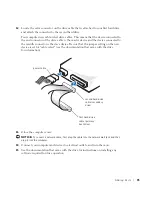
To disconnect a network cable, first unplug the cable from your computer and then 

unplug it from the network wall jack.

3

Disconnect any telephone or telecommunication lines from the computer.

4

Disconnect your computer and all attached devices from their electrical outlets, and 
then press the power button to ground the system board.

  CAUTION: To guard against electrical shock, always unplug your computer from 

the electrical outlet before opening the cover.

5

Open the computer cover (see page 78).
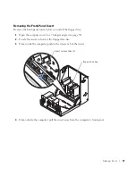
6

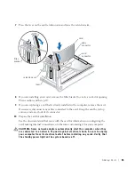
Press the lever on the card retention arm and raise the retention arm (see page 82).

7

If necessary, disconnect any cables connected to the card.

8

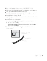
Grasp the card by its top corners, and ease it out of its connector.
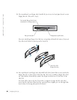
9

If you are removing the card permanently, install a filler bracket in the empty 
card-slot opening.

If you need a filler bracket, contact Dell (see page 113).
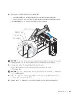
10

Lower the retention arm and press it into place, securing the card(s) in the computer.

 NOTICE: 

To connect a network cable, first plug the cable into the network wall jack and then 

plug it into the computer.
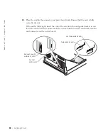
11

Close the computer cover (see page 100), reconnect the computer and devices to 
electrical outlets, and turn them on.

12

Remove the card’s driver from the operating system.

Summary of Contents for Dimension 8300 Series

Page 1: ...or parallel connector keyboard connector USB 2 0 connectors 6 line out connector microphone connector line in connector mouse connector video connector serial connector network adapter CD or DVD activity light CD or DVD drive eject button floppy drive eject button On computers with an optional floppy drive optional sound card connector see the setup diagram diagnostic lights surround connector cen...

Page 2: ..._______________ Information in this document is subject to change without notice 2003 2004 Dell Inc All rights reserved Reproduction inanymannerwhatsoeverwithoutthewrittenpermissionofDellInc isstrictlyforbidden Trademarks used in this text Dell the DELL logo Inspiron Dell Precision Dimension OptiPlex PowerApp PowerEdge PowerConnect PowerVault DellNet Axim and Latitude are trademarks of Dell Inc In...

Page 3: ...ation for Your Computer 13 1 Setting Up and Using Your Computer Setting Up a Printer 18 Printer Cable 18 Connecting a Parallel Printer 18 Connecting a USB Printer 19 Transferring Information to a New Computer 20 Setting Up a Home and Office Network 22 Connecting to a Network Adapter 22 Network Setup Wizard 22 Connecting to the Internet 23 Setting Up Your Internet Connection 23 Copying CDs and DVDs...

Page 4: ...oblems 35 Hard drive problems 35 E Mail Modem and Internet Problems 35 Error Messages 37 General Problems 38 The computer stops responding 38 A program stops responding 38 A program crashes repeatedly 39 A program is designed for an earlier Microsoft Windows operating system 39 A solid blue screen appears 39 Other software problems 39 Other technical problems 40 General hardware problems 40 IEEE 1...

Page 5: ...eshooting Diagnostic Lights 54 Dell Diagnostics 58 When to Use the Dell Diagnostics 58 Starting the Dell Diagnostics 58 Drivers 61 What Is a Driver 61 Identifying Drivers 61 Reinstalling Drivers 62 Using Windows System Restore 63 Creating a Restore Point 63 Restoring the Computer to an Earlier Operating State 64 Undoing the Last System Restore 64 Resolving Software and Hardware Incompatibilities 6...

Page 6: ...stem Board 81 Installing and Removing Cards 82 Installing a Card 82 Removing a Card 86 Adding Memory 87 DDR Memory Overview 87 Memory Installation Guidelines 88 Addressing Memory with 4 GB Configurations 88 Installing Memory 88 Adding or Replacing the AGP Card 91 Removing an AGP Card 91 Installing an AGP Card 92 Adding a Second Hard Drive 93 Adding a Floppy Drive 96 Removing the Front Panel Insert...

Page 7: ...Third Party Software and Peripherals 112 Contacting Dell 113 Regulatory Notices 131 NOM Information Mexico Only 132 Limited Warranties 133 Limited Warranty for Dell Branded Hardware Products U S Only 133 Limited Warranty Terms for Dell Branded Hardware Products Canada Only 136 Dell Software and Peripherals Canada Only 139 1 Year End User Manufacturer Guarantee Latin America and the Caribbean Only ...

Page 8: ...8 Contents ...

Page 9: ...ant RJ 11 modular plug Before you clean your computer disconnect the computer from the electrical outlet Clean your computer with a soft cloth dampened with water Do not use liquid or aerosol cleaners which may contain flammable substances To help avoid possible damage to the system board wait 5 seconds after turning off the computer before disconnecting a device from the computer To avoid shortin...

Page 10: ...itor and attached devices are electrically rated to operate with the AC power available in your location Before working inside the computer unplug the computer to help prevent electric shock or system board damage Certain system board components continue to receive power any time the computer is connected to AC power SAFETY When Working Inside Your Computer Before you open the computer cover perfo...

Page 11: ... as the microprocessor You can do so by touching an unpainted metal surface on the computer chassis As you continue to work inside the computer periodically touch an unpainted metal surface to remove any static charge your body may have accumulated You can also take the following steps to prevent damage from electrostatic discharge ESD Do not remove components from their antistatic packing materia...

Page 12: ...12 Safety Instructions w w w d e l l c o m s u p p o r t d e l l c o m ...

Page 13: ... when shipped from Dell You can use the CD to reinstall drivers see page 62 run the Dell Diagnostics see page 58 or access your documentation Readme files may be included on your CD to provide last minute updates about technical changes to your computer or advanced technical reference material for experienced users or technicians How to set up a printer How to troubleshoot and solve problems How t...

Page 14: ... e The Dell Support website provides several online tools including Solutions Troubleshooting hints and tips articles from technicians and online courses Community Forum Online discussion with other Dell customers Upgrades Upgrade information for components such as memory the hard drive and the operating system Customer Care Contact information order status warranty and repair information Download...

Page 15: ... S y s t e m C D After you reinstall your operating system using the Operating System Reinstallation CD use the ResourceCD to reinstall drivers for the devices that came with your computer The product key for your operating system is located on your computer What are you looking for Find It Here ...

Page 16: ...16 Finding Information for Your Computer w w w d e l l c o m s u p p o r t d e l l c o m ...

Page 17: ...ing Up and Using Your Computer Setting Up a Printer Transferring Information to a New Computer Setting Up a Home and Office Network Connecting to the Internet Copying CDs and DVDs Hyper Threading Turning Off Your Computer ...

Page 18: ...ontact the printer manufacturer for technical assistance Printer Cable Your printer connects to your computer with either a USB cable or a parallel cable Your printer may not come with a printer cable so if you purchase a cable separately ensure that it is compatible with your printer If you purchased a printer cable at the same time you purchased your computer the cable may arrive in the computer...

Page 19: ...Add New Hardware Wizard window appears click Cancel 5 Install the printer driver if necessary See the documentation that came with your printer Connecting a USB Printer NOTE You can connect USB devices while the computer is turned on 1 Complete the operating system setup if you have not already done so 2 Install the printer driver if necessary See the documentation that came with your printer para...

Page 20: ... Microsoft Windows XP operating system provides a Files and Settings Transfer wizard to move data from the source computer to the new computer You can move data such as E mails Toolbar settings Window sizes Internet bookmarks You can transfer the data to the new computer over a network or serial connection or you can store it on a removable medium such as a writable CD or floppy disk USB printer c...

Page 21: ...ional tasks 3 Under What do you want to do click Transfer files and settings 4 On the Files and Settings Transfer Wizard welcome screen click Next 5 On the Which computer is this screen click Old Computer and click Next 6 On the Select a transfer method screen click the transfer method you prefer 7 On the What do you want to transfer screen select the items you want to transfer and click Next Afte...

Page 22: ...twork adapter connector on the back of your computer NOTE Do not use a network cable with a telephone wall jack 2 Connect the other end of the network cable to a network connection device such as a network wall jack Network Setup Wizard The Microsoft Windows XP operating system provides a Network Setup Wizard to guide you through the process of sharing files printers or an Internet connection betw...

Page 23: ...Dial up connections are considerably slower than DSL and cable modem connections DSL connections that provide high speed Internet access through your existing phone line With a DSL connection you can access the Internet and use your phone on the same line simultaneously Cable modem connections that provide high speed Internet access through your local cable TV line If you are using a dial up conne...

Page 24: ...P but you did not receive a setup CD click Set up my connection manually If you have a CD click Use the CD I got from an ISP 5 Click Next If you selected Set up my connection manually continue to step 6 Otherwise follow the instructions on the screen to complete the setup NOTE If you do not know which type of connection to select contact your ISP 6 Click the appropriate option under How do you wan...

Page 25: ...blems check for available software patches at the Sonic support website at support sonic com NOTE Most commercial DVDs have copyright protection and cannot be copied using Sonic RecordNow 1 Click the Start button point to All Programs Sonic RecordNow RecordNow 2 Click either the audio tab or the data tab depending on the kind of CD you are planning to copy 3 Click Exact Copy 4 To copy the CD or DV...

Page 26: ...apacity for example do not copy a 650 MB file to a 650 MB blank CD The CD RW drive needs 1 or 2 MB of the blank CD to finalize the recording Use a blank CD RW to practice CD recording until you are familiar with CD recording techniques If you make a mistake you can erase the data on the CD RW and try again You can also use blank CD RWs to test music file projects before you record the project perm...

Page 27: ...tem setup program For more information on accessing the system setup program see page 107 For more information on Hyper Threading search the Knowledge Base on the Dell Support website at support dell com Turning Off Your Computer NOTICE To avoid losing data turn off your computer by performing a Microsoft Windows operating system shutdown as described next rather than by pressing the power button ...

Page 28: ...28 Setting Up and Using Your Computer w w w d e l l c o m s u p p o r t d e l l c o m ...

Page 29: ...Battery Problems Drive Problems E Mail Modem and Internet Problems Error Messages General Problems IEEE 1394 Device Problems Keyboard Problems Mouse Problems Network Problems Power Problems Printer Problems Scanner Problems Sound and Speaker Problems Video and Monitor Problems ...

Page 30: ...ult to figure out where to go for answers Use this chart to help you quickly find the answers to your questions See page 44 See page 37 Get technical assistance from Dell See page 113 Press a key or move the mouse See the Tell Me How help file for information on standby mode For more information see page 44 ...

Page 31: ...Solving Problems 31 See page 50 See page 48 See page 46 See page 35 See page 42 See page 42 See page 33 See page 44 See page 38 See page 47 See page 37 See page 35 See page 35 See page 38 ...

Page 32: ...ick the Start button and click Help and Support 2 Click User and system guides and click User s guides 3 Click Tell Me How TO ACCESS WINDOWS HELP 1 Click the Start button and click Help and Support 2 Type a word or phrase that describes your problem and click the arrow icon 3 Click the topic that describes your problem 4 Follow the instructions shown on the screen TO LOCATE ADDITIONAL INFORMATION ...

Page 33: ...virus software to check for and remove viruses Viruses can sometimes prevent Windows from recognizing the drive TEST THE DRIVE Insert another disk to eliminate the possibility that the original floppy disk is defective Insert a bootable floppy disk and reboot the computer ENSURE THAT THE DISK IS NOT FULL OR WRITE PROTECTED Ensure that the disk has available space and that it is not write protected...

Page 34: ...WOOFER See Sound and Speaker Problems on page 48 ENSURE THAT WINDOWS RECOGNIZES THE DRIVE Click the Start button and click My Computer If the CD drive is not listed perform a full scan with your antivirus software to check for and remove viruses Viruses can sometimes prevent Windows from recognizing the drive CLEAN THE DISC See the Tell Me How help file for instructions on cleaning your CDs To acc...

Page 35: ...with your antivirus software to check for and remove viruses Viruses can sometimes prevent Windows from recognizing the drive CLEAN THE DISC See the Tell Me How help file for instructions on cleaning your DVDs To access help files see page 32 CHECK FOR INTERRUPT REQUEST CONFLICTS See page 65 RUN CHECK DISK 1 Click the Start button and click My Computer 2 Right click the drive letter local disk tha...

Page 36: ...ailable on all computers VERIFY THAT THE MODEM IS COMMUNICATING WITH WINDOWS 1 Click the Start button and click Control Panel 2 Click Printers and Other Hardware 3 Click Phone and Modem Options 4 Click the Modems tab 5 Click the COM port for your modem 6 Click Properties click the Diagnostics tab and then click Query Modem to verify that the modem is communicating with Windows If all commands rece...

Page 37: ...ternet service provider for assistance A FILENAME CANNOT CONTAIN ANY OF THE FOLLOWING CHARACTERS Do not use these characters in filenames A REQUIRED DLL FILE WAS NOT FOUND The program that you are trying to open is missing an essential file To remove and then reinstall the program 1 Click the Start button and click Control Panel 2 Click Add or Remove Programs 3 Select the program you want to remov...

Page 38: ...ou are trying to copy is too large to fit on the disk Try copying the file to a blank disk or using a larger capacity disk x IS NOT ACCESSIBLE THE DEVICE IS NOT READY The floppy drive cannot read the disk Insert a floppy disk into the drive and try again TURN THE COMPUTER OFF If your computer locks up and you are unable to get a response by pressing a key on your keyboard or moving your mouse pres...

Page 39: ...nvironments 1 Click the Start button point to All Programs Accessories and then click Program Compatibility Wizard 2 In the welcome screen click Next 3 Follow the instructions on the screen TURN THE COMPUTER OFF If the computer does not respond to a keystroke or a proper shutdown press the power button for at least 8 to 10 seconds until the computer turns off Press the power button again to restar...

Page 40: ...he software documentation for information If necessary uninstall and then reinstall the program ENSURE THAT YOU PROPERLY INSTALLED AND CONFIGURED THE PROGRAM Seethe software documentation for information If necessary uninstall and then reinstall the program GO TO THE DELL SUPPORT WEBSITE Go to support dell com for help with general usage installation and troubleshooting questions The support websi...

Page 41: ...ion and troubleshooting instructions If the problem persists contact the hardware manufacturer for technical assistance CHECK YOUR OPERATING SYSTEM DOCUMENTATION FOR ADDITIONAL TROUBLESHOOTING INFORMATION CHECK FOR INTERRUPT REQUEST CONFLICTS See page 65 CHECK THE IEEE 1394 DEVICE Ensure that the IEEE 1394 device is properly inserted into the connector ENSURE THAT THE IEEE 1394 DEVICE IS RECOGNIZE...

Page 42: ...he computer see page 27 reconnect the keyboard cable as shown on the Start Here setup diagram for your computer and then restart the computer Check the cable connector for bent or broken pins and for damaged or frayed cables Straighten bent pins Remove keyboard extension cables and connect the keyboard directly to the computer TEST THE KEYBOARD Connect a properly working keyboard to the computer a...

Page 43: ...While your computer is on remove the power cable from the back of the computer 2 Connect the mouse to the computer 3 Reconnect the power cable 4 Turn on your computer Pressing the power button does not clear the computer s settings and does not restore mouse functionality CHECK THE MOUSE CABLE Check the cable connector for bent or broken pins and for damaged or frayed cables Straighten bent pins E...

Page 44: ...D TRY TO LOG ON TO THE NETWORK AGAIN CHECK YOUR NETWORK SETTINGS Contact your network administrator or the person who set up your network to verify that your network settings are correct and that the network is functioning CHECK FOR INTERRUPT REQUEST CONFLICTS See page 65 ADJUST THE POWER PROPERTIES Your computer may be in standby or hibernate mode For information on power conservation modes see t...

Page 45: ...he front panel cable is securely connected to the system board see page 81 If the problem persists contact Dell see page 113 IF THE POWER LIGHT IS AMBER AND GREEN The computer is receiving electrical power but an internal power problem might exist Ensure that the microprocessor power cable is securely connected to the system board see page 81 Remove and then reinstall the memory modules see page 8...

Page 46: ...tension cables Too many devices on a power strip Multiple power strips connected to the same electrical outlet CHECK THE PRINTER DOCUMENTATION See the printer documentation for setup and troubleshooting information ENSURE THAT THE PRINTER IS TURNED ON See the printer documentation for power button information VERIFY THE PRINTER CABLE CONNECTIONS See the printer documentation for cable connection i...

Page 47: ...t to the following port s setting is LPT1 Printer Port For a USB printer ensure that the Print to the following port s setting is USB REINSTALL THE PRINTER DRIVER See the printer documentation for instructions CHECK THE SCANNER DOCUMENTATION See the scanner documentation for setup and troubleshooting information UNLOCK THE SCANNER Ensure that your scanner is unlocked if it has a locking tab or but...

Page 48: ...t the speakers are connected as shown on the setup diagram supplied with the speakers If you purchased a sound card ensure that the speakers are connected to the card ENSURE THAT THE SUBWOOFER AND THE SPEAKERS ARE TURNED ON See the setup diagram supplied with the speakers If your speakers have volume controls adjust the volume bass or treble to eliminate distortion ADJUST THE WINDOWS VOLUME CONTRO...

Page 49: ...mentation for diagnostics instructions REINSTALL THE AUDIO SOUND DRIVER See page 62 CHECK FOR INTERRUPT REQUEST CONFLICTS See page 65 CHECK THE HEADPHONE CABLE CONNECTION Ensure that the headphone cable is securely inserted into the headphone connector see page 70 DISABLE DIGITAL MODE Your headphones do not work if the CD drive is operating in digital mode To disable digital mode 1 Click the Start...

Page 50: ...art Here setup diagram for your computer TEST THE ELECTRICAL OUTLET Ensure that the electrical outlet is working by testing it with another device such as a lamp SWAP THE POWER CABLES Swap the computer and monitor power cables to determine if the power cable is defective TEST THE VIDEO EXTENSION CABLE IF USED If you are using a video extension cable and removing the cable solves the problem the ca...

Page 51: ...NT DIRECTION Eliminate sunlight glare which can cause poor picture quality ADJUST THE WINDOWS DISPLAY SETTINGS 1 Click the Start button and click Control Panel 2 Click Appearance and Themes 3 Click Display and click the Settings tab 4 Try different settings for Screen resolution and Color quality RESTORE THE RECOMMENDED SETTINGS Restore the original resolution and refresh rate settings See the Tel...

Page 52: ...52 Solving Problems w w w d e l l c o m s u p p o r t d e l l c o m ...

Page 53: ...S E C T I O N 3 Advanced Troubleshooting Diagnostic Lights Dell Diagnostics Drivers Using Windows System Restore Resolving Software and Hardware Incompatibilities Reinstalling Microsoft Windows XP ...

Page 54: ... The computer is in a normal off condition or a possible pre BIOS failure has occurred Verify that the computer is plugged into a working electrical outlet and that you have pressed the power button Memory modules are detected but a memory failure has occurred If you have one memory module installed reinstall it see page 87 and restart the computer If you have two or more memory modules installed ...

Page 55: ...lving Software and Hardware Incompatibilities on page 65 4 If the problem persists contact Dell see page 113 A possible video card failure has occurred If the computer has a video card remove the card and reinstall it see page 91 and restart the computer If the problem still exists install a video card that you know works and restart the computer If the problem persists or the computer has integra...

Page 56: ... restart the computer If the computer starts normally move the memory module to a different connector and restart the computer Continue until you have identified a faulty connector or reinstalled all modules without error Memory modules are detected but a memory configuration or compatibility error exists Ensure that there are no special memory module memory connector placement requirements see pa...

Page 57: ...em with a device such as the floppy drive or hard drive check the device to make sure it is functioning properly The operating system is attempting to boot from a device such as a floppy drive or hard drive check system setup see page 107 to make sure that the boot sequence is correct for the devices installed on your computer The computer is in a normal operating condition after POST None Light P...

Page 58: ... information that describes the tests and devices Receive status messages that tell you whether tests completed successfully Receive error messages if problems are detected Starting the Dell Diagnostics NOTICE Use the Dell Diagnostics to test your Dell computer only Using this program with other computers can result in error messages Start the Dell Diagnostics from either your hard drive see page ...

Page 59: ...ugh the Start menu and try again NOTE This feature changes the boot sequence for one time only On the next start up the computer boots according to the devices specified in the system setup program 3 When the boot device list appears highlight IDE CD ROM Device and press Enter 4 Select the IDE CD ROM Device option from the CD boot menu 5 Select the Boot from CD ROM option from the menu that appear...

Page 60: ... problem quickly Extended Test Performs a thorough check of devices This test typically takes an hour or more and requires you to answer questions periodically Custom Test Tests a specific device You can customize the tests you want to run Symptom Tree Lists the most common symptoms encountered and allows you to select a test based on the symptom of the problem you are having Tab Function Results ...

Page 61: ...required drivers already installed no further installation or configuration is needed NOTICE The Dell Dimension ResourceCD may contain drivers for operating systems that are not on your computer Ensure that you are installing software appropriate for your operating system Many drivers such as the keyboard driver come with your Microsoft Windows operating system You may need to install drivers if y...

Page 62: ...h the previously installed version 1 Click the Start button and click Control Panel 2 Under Pick a Category click Performance and Maintenance 3 Click System 4 In the System Properties window click the Hardware tab 5 Click Device Manager 6 Right click the device for which the new driver was installed and click Properties 7 Click the Drivers tab 8 Click Roll Back Driver If Device Driver Rollback doe...

Page 63: ...the My Drivers The ResourceCD has identified these components in your system window 6 Click the driver that you want to reinstall and follow the instructions on the screen If a particular driver is not listed then that driver is not required by your operating system Using Windows System Restore The Microsoft Windows XP operating system provides System Restore to allow you to return your computer t...

Page 64: ...l calendar dates with available restore points appear in bold 4 Select a restore point and click Next If a calendar date has only one restore point then that restore point is automatically selected If two or more restore points are available click the restore point that you prefer 5 Click Next The Restoration Complete screen appears after System Restore finishes collecting data and then the comput...

Page 65: ...dows XP 1 Click the Start button and click Control Panel 2 Click Performance and Maintenance and click System 3 Click the Hardware tab and click Device Manager 4 In the Device Manager list check for conflicts with the other devices Conflicts are indicated by a yellow exclamation point beside the conflicting device or a red X if the device has been disabled 5 Double click any conflict to display th...

Page 66: ...he computer To reinstall Windows XP you need the following items Dell Operating System CD Dell ResourceCD NOTE The ResourceCD contains drivers that were installed during assembly of the computer Use the ResourceCD to load any required drivers Reinstalling Windows XP To reinstall Windows XP perform all the steps in the following sections in the order in which they are listed The reinstallation proc...

Page 67: ...license agreement 3 If your computer already has Windows XP installed and you want to recover your current Windows XP data type r to select the repair option and remove the CD 4 If you want to install a new copy of Windows XP press Esc to select that option 5 Press Enter to select the highlighted partition recommended and follow the instructions on the screen The Windows XP Setup screen appears an...

Page 68: ...ion enter your selections If you are unsure of your settings accept the default selections Windows XP installs the operating system components and configures the computer The computer automatically restarts NOTICE Do not press any key when the following message appears Press any key to boot from the CD 13 When the Welcome to Microsoft screen appears click Next 14 When the How will this computer co...

Page 69: ...omputer Reattaching the Front Door and Hinge Arms Opening the Computer Cover Looking Inside Your Computer Installing and Removing Cards Adding Memory Adding or Replacing the AGP Card Adding a Second Hard Drive Adding a Floppy Drive Closing the Computer Cover ...

Page 70: ...70 Adding Parts w w w d e l l c o m s u p p o r t d e l l c o m Front and Back View of the Computer Front View 1 2 4 3 5 6 7 8 9 10 On computers with an optional floppy drive ...

Page 71: ...ight might also be on when devices such as your CD player are operating 6 power button Press this button to turn on the computer NOTICE To avoid losing data do not use the power button to turn off the computer Instead perform a Microsoft Windows shutdown 7 service tag The tag is used to identify your computer when you access the Dell Support website or call technical support 8 headphone connector ...

Page 72: ...72 Adding Parts w w w d e l l c o m s u p p o r t d e l l c o m Back View 2 1 3 11 12 10 7 5 8 16 14 6 9 13 15 4 ...

Page 73: ...n connector Use the blue line in connector to attach a record playback device such as a cassette player CD player or VCR On computers with a sound card the line in connector is on the card 8 video connector Plug the cable from your monitor into the blue connector 9 optional sound card connector If you purchased the optional sound card plug your sound equipment speakers a microphone and so on into ...

Page 74: ...gram On computers with a sound card the microphone connector is on the card 13 line out connector Use the green line out connector to attach headphones and most speakers with integrated amplifiers On computers with a sound card the line out connector is on the card 14 center LFE connector Use the yellow center Low Frequency Effects LFE connector to attach your subwoofer On computers with a sound c...

Page 75: ...ey are detached Reattaching the Hinge Arms CAUTION Before you begin any of the procedures in this section follow the safety instructions on page 9 1 Shut down the computer through the Start menu see page 27 2 Disconnect the computer power cable from the electrical outlet 3 Remove the front panel door by gently snapping it off the two hinge arms 4 Remove the front panel insert above the door bay ar...

Page 76: ...al at the back of the computer While you work periodically touch an unpainted metal surface to dissipate any static electricity that could harm internal components 7 Pull the arms toward you until they snap into position If the hinge arms do not snap back into position on the first attempt slightly reposition the arms and try again 8 After the hinge arms snap into position lower and raise the arms...

Page 77: ...n follow the safety instructions on page 9 1 Shut down the computer through the Start menu see page 27 2 Disconnect the computer power cable from the electrical outlet 3 Lower the hinge arms to the vertical position 4 Align the two clips on the inside of the front door with the two hinge arms 5 Press inward on the front door until it clips to both hinge arms hinge arms 2 in vertical position front...

Page 78: ...To disconnect a network cable first unplug the cable from your computer and then unplug it from the network wall jack 3 Disconnect any telephone or telecommunication lines from the computer 4 Disconnect your computer and all attached devices from their electrical outlets and then press the power button to ground the system board CAUTION To guard against electrical shock always unplug your computer...

Page 79: ...ile pulling up on the top of the cover with the other hand b Press the release button on the left side of the computer with one hand while pulling up on the top of the cover with the other hand c Hold the bottom of the computer with one hand and then pull open the cover with the other hand back of computer release button release button arrow ...

Page 80: ...this section follow the safety instructions on page 9 NOTICE Be careful when opening the computer cover to ensure that you do not inadvertently disconnect cables from the system board system board page 81 hard drive page 93 drive cables power cables power supply computer cover page 78 and page 100 Depending on the types of drives installed in your computer the cover may not open as widely as shown...

Page 81: ... modem connector TELE front panel audio cable connector FP_AUDIO CD audio connector CD memory module connectors DIMM3 DIMM4 page 87 AGP slot connector AGP back of computer On computers with optional integrated sound CD drive connector SEC IDE battery socket BATTERY page 110 hard drive connector PRI IDE password jumper PASSWORD front panel connector FRONT_PANEL serial ATA connectors SATA_0 and SATA...

Page 82: ...uctions on page 10 1 If you are replacing a card remove the current driver for the card from the operating system 2 Shut down the computer through the Start menu see page 27 3 Ensure that your computer and attached devices are turned off If your computer and attached devices did not automatically turn off when you shut down your computer turn them off now NOTICE To disconnect a network cable first...

Page 83: ...s and ease it out of its connector 10 Prepare the card for installation See the documentation that came with the card for information on configuring the card making internal connections or otherwise customizing it for your computer CAUTION Some network adapters automatically start the computer when they are connected to a network To guard against electrical shock be sure to unplug your computer fr...

Page 84: ...e card is fully seated in the slot If the card is full length insert the end of the card into the card guide bracket as you lower the card toward its connector on the system board Insert the card firmly into the card connector on the system board fully seated card not fully seated card bracket caught outside of slot bracket within slot ...

Page 85: ...computer cover from closing properly or cause damage to the equipment 13 Connect any cables that should be attached to the card See the documentation for the card for information about the card s cable connections NOTICE To connect a network cable first plug the cable into the network wall jack and then plug it into the computer 14 Close the computer cover see page 100 reconnect the computer and d...

Page 86: ... button to ground the system board CAUTION To guard against electrical shock always unplug your computer from the electrical outlet before opening the cover 5 Open the computer cover see page 78 6 Press the lever on the card retention arm and raise the retention arm see page 82 7 If necessary disconnect any cables connected to the card 8 Grasp the card by its top corners and ease it out of its con...

Page 87: ...tched pairs the computer will continue to operate but with a slight reduction in performance NOTE Always install DDR memory modules in the order indicated on the system board The recommended memory configurations are A pair of matched memory modules installed in connectors DIMM1 and DIMM2 or A pair of matched memory modules installed in connectors DIMM1 and DIMM2 and another matched pair installed...

Page 88: ...rrent operating systems such as Microsoft Windows XP can only use a maximum of 4 GB of address space however the amount of memory available to the operating system is less than 4 GB Certain components within the computer require address space in the 4 GB range Any address space reserved for these components cannot be used by computer memory Installing Memory CAUTION Before you begin any of the pro...

Page 89: ... 5 Open the computer cover see page 78 6 Lay the computer on its side so that the system board is on the bottom of the inside of the computer 7 If necessary remove a memory module a Press out the securing clip at each end of the memory module connector b Grasp the module and pull up If the module is difficult to remove gently ease the module back and forth to remove it from the connector 8 To inse...

Page 90: ...its into the vertical guides at each end of the connector Press firmly on the ends of the module until it snaps into place If you insert the module correctly the securing clips snap into the cutouts at each end of the module 11 Replace the computer cover see page 100 NOTICE To connect a network cable first plug the cable into the network wall jack and then plug it into the computer 12 Connect your...

Page 91: ...ttached devices did not automatically turn off when you shut down your computer turn them off now NOTICE To disconnect a network cable first unplug the cable from your computer and then unplug it from the network wall jack 3 Disconnect any telephone or telecommunication lines from the computer 4 Disconnect your computer and all attached devices from their electrical outlets and then press the powe...

Page 92: ...ctor and gently press the card into the AGP connector until it clicks into place 2 Release the card lever ensuring that the tab fits into the notch on the front end of the card 3 Secure the card by lowering the hinged lever on the back panel 4 Close the computer cover see page 100 tab card clip lever notch PCI connector AGP connector back of computer card clip lever AGP card card clip slot connect...

Page 93: ...es did not automatically turn off when you shut down your computer turn them off now NOTICE To disconnect a network cable first unplug the cable from your computer and then unplug it from the network wall jack 4 Disconnect any telephone or telecommunication lines from the computer 5 Disconnect your computer and all attached devices from their electrical outlets and then press the power button to g...

Page 94: ...ull the first hard drive out of the upper bay c Gently slide the first hard drive into the lower bay until you hear a click d Reconnect the power and hard drive cables to the back of the first hard drive 10 Gently slide the new hard drive into the upper bay until you hear a click 11 Connect a power cable to the drive NOTICE Match the colored strip on the cable with pin 1 on the drive rail tabs 2 s...

Page 95: ... sure that the jumper setting on the new device is set for cable select see the documentation that came with the drive for information 13 Close the computer cover NOTICE To connect a network cable first plug the cable into the network wall jack and then plug it into the computer 14 Connect your computer and devices to electrical outlets and turn them on 15 See the documentation that came with the ...

Page 96: ...atically turn off when you shut down your computer turn them off now NOTICE To disconnect a network cable first unplug the cable from your computer and then unplug it from the network wall jack 3 Disconnect any telephone or telecommunication lines from the computer 4 Disconnect your computer and all attached devices from their electrical outlets and then press the power button to ground the system...

Page 97: ...ppy drive 1 Open the computer cover to a 90 degree angle see page 78 2 Locate the insert in front of the floppy drive bay 3 From inside the computer push in the release tab of the insert 4 From outside the computer pull the insert away from the computer s front panel floppy drive bay insert release tabs 4 ...

Page 98: ...he insert that you received in the floppy drive kit over the front of the drive bay If you are installing a floppy drive that was not purchased from Dell reattach the empty insert frame over the front of the drive bay To attach either insert face the front of the computer and slip the left side of the insert into the left side of the drive bay opening Then slightly press in the right side insert r...

Page 99: ...loppy drive power cable to the floppy drive 4 Check all cable connections and fold cables out of the way to provide airflow for the fan and cooling vents 5 Close the computer cover see page 100 NOTICE To connect a network cable first plug the cable into the network wall jack and then plug it into the computer 6 Connect your computer and devices to electrical outlets and turn them on 7 After you tu...

Page 100: ...or instructions on installing any software required for drive operation Closing the Computer Cover 1 Ensure that all cables are connected and fold cables out of the way Gently pull the power cables toward you so that they do not get caught underneath the drives 2 Ensure that no tools or extra parts are left inside the computer 3 Close the cover a Pivot the cover down b Press down on the right side...

Page 101: ...S E C T I O N 5 Appendix Specifications Standard Settings Clearing Forgotten Passwords Replacing the Battery Dell Technical Support Policy U S Only Contacting Dell Regulatory Notices Limited Warranties ...

Page 102: ...tion supporting Hyper Threading technology Memory Type DDR 333 or 400 non ECC Memory connectors four Memory capacities 128 256 512 MB and 1 GB non ECC Minimum memory 256 MB Maximum memory 4 GB BIOS address F8000h Computer Information System chip set Intel 875P DMA channels eight Interrupt levels 15 BIOS chip 4 Mb NIC integrated PCI Network Interface System clock 533 or 800 MHz data rate Video Type...

Page 103: ...4x 2x modes at 1 5 V PCI connectors four connector size 120 pins connector data width maximum 32 bits Drives Externally accessible two 3 5 inch bays two 5 25 inch bays Available devices ATA 66 or ATA 100 Ultra DMA hard drive serial ATA drive CD drive Zip drive DVD drive CD RW drive DVD CD RW combo drive and DVD RW drive Internally accessible two bays for 1 inch high hard drives ...

Page 104: ... computers with integrated sound capabilities System board connectors Primary IDE channel 40 pin connector on PCI local bus Secondary IDE channel 40 pin connector on PCI local bus Serial ATA drive two 7 pin connectors Floppy drive 34 pin connector Telephony ATAPI 4 pin connector CD Audio ATAPI 4 pin connector Fan 3 pin connector Controls and Lights Power control push button Power light green light...

Page 105: ... Temperature Operating 10 to 35 C 50 to 95 F NOTE At 35 C 95 F the maximum operating altitude is 914 m 3000 ft Storage 40 to 65 C 40 to 149 F Relative humidity 20 to 80 noncondensing Maximum vibration Operating 0 25 G at 3 to 200 Hz at 1 2 octave min Storage 0 5 G at 3 to 200 Hz at 1 2 octave min Maximum shock Operating bottom half sine pulse with a change in velocity of 50 8 cm sec 20 inches sec ...

Page 106: ...system setup program contains the standard settings for your computer NOTICE Unless you are an expert computer user do not change the settings for this program Certain changes might make your computer work incorrectly See the following figure for an example of the main program screen ...

Page 107: ...2 cache service tag and the version number of the BIOS Options A scrollable box listing options that define the configuration of your computer including installed hardware power conservation and security features Fields to the right of the option titles contain settings or values The fields that you can change appear bright on the screen The fields that you cannot change because they are set by th...

Page 108: ...crosoft Windows desktop Shut down your computer see page 27 and try again The Boot Device Menu appears listing all available boot devices Each device has a number next to it 3 At the bottom of the menu enter the number of the device that is to be used for the current boot only Changing Boot Sequence for Future Boots 1 Enter the system setup program see page 107 2 Use the arrow keys to highlight th...

Page 109: ...e wall outlet and then press the power button to ground the system board CAUTION To guard against electrical shock always unplug your computer from the electrical outlet before opening the cover 4 Open the computer cover see page 78 5 Locate jumper PSWD on the system board see page 81 and remove the jumper plug 6 Close the computer cover see page 100 plug your computer into an electrical outlet an...

Page 110: ...e if it is incorrectly installed Replace the battery only with the same or equivalent type recommended by the manufacturer Discard used batteries according to the manufacturer s instructions To replace the battery 1 Record all the screens in system setup see page 106 so that you can restore the correct settings in step 12 2 Shut down the computer through the Start menu 3 Ensure that your computer ...

Page 111: ...attempt to pry out the battery Otherwise you may damage the system board by prying off the socket or by breaking circuit traces on the system board 8 Remove the battery by carefully prying it out of its socket with your fingers or with a blunt nonconducting object such as a plastic screwdriver 9 Insert the new battery into the socket with the side labeled facing up and snap the battery into place ...

Page 112: ...y optional support service contract purchased with the computer 2 All Dell standard components included in a Custom Factory Integration CFI project are covered by the standard Dell limited warranty for your computer However Dell also extends a parts replacement program to cover all nonstandard third party hardware components integrated through CFI for the duration of the computer s service contrac...

Page 113: ...ctronic addresses telephone numbers and codes provided in the following table If you need assistance in determining which codes to use contact a local or an international operator Country City International Access Code Country Code City Code Department Name or Service Area Website and E Mail Address Area Codes Local Numbers and Toll Free Numbers Anguilla General Support toll free 800 335 0031 Anti...

Page 114: ...Small Business Fax 0820 240 530 49 Home Small Business Customer Care 0820 240 530 14 Preferred Accounts Corporate Customer Care 0820 240 530 16 Home Small Business Technical Support 0820 240 530 14 Preferred Accounts Corporate Technical Support 0660 8779 Switchboard 0820 240 530 00 Bahamas General Support toll free 1 866 278 6818 Barbados General Support 1 800 534 3066 Belgium Brussels Internation...

Page 115: ...al support toll free 1 800 247 9362 TechFax toll free 1 800 950 1329 Customer Care Home Sales Small Business toll free 1 800 847 4096 Customer Care med large business government toll free 1 800 326 9463 Technical Support Home Sales Small Business toll free 1 800 847 4096 Technical Support med large bus government toll free 1 800 387 5757 Sales Home Sales Small Business toll free 1 800 387 5752 Sal...

Page 116: ...Large Corporate Accounts GCP toll free 800 858 2055 Large Corporate Accounts Key Accounts toll free 800 858 2628 Large Corporate Accounts North toll free 800 858 2999 Large Corporate Accounts North Government and Education toll free 800 858 2955 Large Corporate Accounts East toll free 800 858 2020 Large Corporate Accounts East Government and Education toll free 800 858 2669 Large Corporate Account...

Page 117: ...l com E mail Support servers Nordic_server_support dell com Technical Support 7023 0182 Customer Care Relational 7023 0184 Home Small Business Customer Care 3287 5505 Switchboard Relational 3287 1200 Fax Switchboard Relational 3287 1201 Switchboard Home Small Business 3287 5000 Fax Switchboard Home Small Business 3287 5001 Dominica General Support toll free 1 866 278 6821 Dominican Republic Genera...

Page 118: ...ional Access Code 00 Country Code 33 City Codes 1 4 Website support euro dell com E mail support euro dell com fr fr emaildell Home and Small Business Technical Support 0825 387 270 Customer Care 0825 823 833 Switchboard 0825 004 700 Switchboard calls from outside of France 04 99 75 40 00 Sales 0825 004 700 Fax 0825 004 701 Fax calls from outside of France 04 99 75 40 01 Corporate Technical Suppor...

Page 119: ...er Care 06103 766 9555 Switchboard 06103 766 7000 Greece International Access Code 00 Country Code 30 Website support euro dell com E mail support euro dell com gr en emaildell Technical Support 080044149518 Gold Technical Support 08844140083 Switchboard 2108129800 Sales 2108129800 Fax 2108129812 Grenada General Support toll free 1 866 540 3355 Guatemala General Support 1 800 999 0136 Guyana Gener...

Page 120: ...al Support 1600 33 8045 Sales 1600 33 8044 Ireland Cherrywood International Access Code 16 Country Code 353 City Code 1 Website support euro dell com E mail dell_direct_support dell com Technical Support 1850 543 543 U K Technical Support dial within U K only 0870 908 0800 Home User Customer Care 01 204 4014 Small Business Customer Care 01 204 4014 U K Customer Care dial within U K only 0870 906 0...

Page 121: ...stomer Care 02 696 821 14 Fax 02 696 821 13 Switchboard 02 696 821 12 Corporate Technical Support 02 577 826 90 Customer Care 02 577 825 55 Fax 02 575 035 30 Switchboard 02 577 821 Jamaica General Support dial from within Jamaica only 1 800 682 3639 Country City International Access Code Country Code City Code Department Name or Service Area Website and E Mail Address Area Codes Local Numbers and ...

Page 122: ...556 3490 24 Hour Automated Order Service 044 556 3801 Customer Care 044 556 4240 Business Sales Division up to 400 employees 044 556 1465 Preferred Accounts Division Sales over 400 employees 044 556 3433 Large Corporate Accounts Sales over 3500 employees 044 556 3430 Public Sales government agencies educational institutions and medical institutions 044 556 1469 Global Segment Japan 044 556 3469 In...

Page 123: ... 91 00 Customer Care Brussels Belgium 02 481 91 19 Fax Brussels Belgium 02 481 92 99 Switchboard Brussels Belgium 02 481 91 00 Macao Country Code 853 Technical Support toll free 0800 582 Customer Service Penang Malaysia 604 633 4949 Transaction Sales toll free 0800 581 Malaysia Penang International Access Code 00 Country Code 60 City Code 4 Technical Support Dell Precision OptiPlex and Latitude to...

Page 124: ...nl_server_support dell com Latitude nl_latitude_support dell com Inspiron nl_inspiron_support dell com Dimension nl_dimension_support dell com OptiPlex nl_optiplex_support dell com Dell Precision nl_workstation_support dell com Technical Support 020 674 45 00 Technical Support Fax 020 674 47 66 Home Small Business Customer Care 020 674 42 00 Relational Customer Care 020 674 4325 Home Small Busines...

Page 125: ...rt servers nordic_server_support dell com Technical Support 671 16882 Relational Customer Care 671 17514 Home Small Business Customer Care 23162298 Switchboard 671 16800 Fax Switchboard 671 16865 Panama General Support 001 800 507 0962 Peru General Support 0800 50 669 Poland Warsaw International Access Code 011 Country Code 48 City Code 22 Website support euro dell com E mail pl_support_tech dell ...

Page 126: ...rnational Access Code 005 Country Code 65 Technical Support toll free 800 6011 051 Customer Service Penang Malaysia 604 633 4949 Transaction Sales toll free 800 6011 054 Corporate Sales toll free 800 6011 053 South Africa Johannesburg International Access Code 09 091 Country Code 27 City Code 11 Website support euro dell com E mail dell_za_support dell com Technical Support 011 709 7710 Customer C...

Page 127: ...de 00 Country Code 46 City Code 8 Website support euro dell com E mail swe_support dell com E mail Support for Latitude and Inspiron Swe nbk_kats dell com E mail Support for OptiPlex Swe_kats dell com E mail Support for Servers Nordic_server_support dell com Technical Support 08 590 05 199 Relational Customer Care 08 590 05 642 Home Small Business Customer Care 08 587 70 527 Employee Purchase Prog...

Page 128: ...01 01 Taiwan International Access Code 002 Country Code 886 Technical Support portable and desktop computers toll free 00801 86 1011 Technical Support servers toll free 0080 60 1256 Transaction Sales toll free 0080 651 228 Corporate Sales toll free 0080 651 227 Thailand International Access Code 001 Country Code 66 Technical Support toll free 0880 060 07 Customer Service Penang Malaysia 604 633 49...

Page 129: ...ness Customer Care 0870 906 0010 Corporate Customer Care 01344 373 185 Preferred Accounts 500 5000 employees Customer Care 0870 906 0010 Central Government Customer Care 01344 373 193 Local Government Education Customer Care 01344 373 199 Health Customer Care 01344 373 194 Home and Small Business Sales 0870 907 4000 Corporate Public Sector Sales 01344 860 456 Home and Small Business Fax 0870 907 4...

Page 130: ...ase Program EPP Customers toll free 1 800 695 8133 Printers and Projectors Technical Support toll free 1 877 459 7298 Public government education and healthcare Customer Service and Technical Support toll free 1 800 456 3355 Employee Purchase Program EPP Customers toll free 1 800 234 1490 Dell Sales toll free 1 800 289 3355 or toll free 1 800 879 3355 Dell Outlet Store Dell refurbished computers t...

Page 131: ...ly together in the electronic environment While this computer has been designed and determined to be compliant with regulatory agency limits for EMI there is no guarantee that interference will not occur in a particular installation If this equipment does cause interference with radio communications services which can be determined by turning the equipment off and on you are encouraged to try to c...

Page 132: ...NOM Exporter Dell Inc One Dell Way Round Rock TX 78682 Importer Dell Computer de México S A de C V Paseo de la Reforma 2620 11 Piso Col Lomas Altas 11950 México D F Ship to Dell Computer de México S A de C V Dell Computer de México S A de C V al Cuidado de Kuehne Nagel de México S de R L Avenida Soles No 55 Col Peñon de los Baños 15520 México D F Model number DHM Supply voltage 115 230 VAC Frequen...

Page 133: ...Failure to follow the product instructions or failure to perform preventive maintenance Problems caused by using accessories parts or components not supplied by Dell Products with missing or altered Service Tags or serial numbers Products for which Dell has not received payment THIS WARRANTY GIVES YOU SPECIFIC LEGAL RIGHTS AND YOU MAY ALSO HAVE OTHER RIGHTS WHICH VARY FROM STATE TO STATE OR JURISD...

Page 134: ...ich such parts are installed The limited warranty on all Dell branded products begins on the date of the packing slip or invoice The warranty period is not extended if we repair or replace a warranted product or any parts Dell may change the availability of limited warranties at its discretion but any changes will not be retroactive What do I do if I need warranty service Before the warranty expir...

Page 135: ...we will replace any defective part with new or refurbished parts if we agree that it needs to be replaced When you contact us we will require a valid credit card number at the time you request a replacement part but we will not charge you for the replacement part as long as you return the original part to us within 30 days after we ship the replacement part to you If we do not receive the original...

Page 136: ...d software added to the Dell branded hardware products through our factory integration system or the reloading of the software Non Dell branded and Solution Provider Direct products and accessories Problems that result from External causes such as accident abuse misuse or problems with electrical power Servicing not authorized by Dell Usage that is not in accordance with product instructions Failu...

Page 137: ...imited warranty begins on the date of the invoice The warranty period is not extended if we repair or replace a warranted product or any parts Dell may change the terms and availability of limited warranties at its discretion but any changes will not be retroactive that is the warranty terms in place at the time of purchase will apply to your purchase What do I do if I need warranty service Before...

Page 138: ...shed parts if we agree that it needs to be replaced When you contact us we will require a valid credit card number at the time you request a replacement part but we will not charge you for the replacement part as long as you return the original part to us within 30 days after we ship the replacement part to you If we do not receive the original part within 30 days we will charge to your credit car...

Page 139: ...of the products we offer work with any or all of the various models of Dell computers nor do we test or guarantee all of the products we sell on the hundreds of different brands of computers available today If you have questions about compatibility we recommend and encourage you to contact the third party software and peripheral product manufacturer or publisher directly Dell Branded Peripheral Pr...

Page 140: ...d above and the return number provided to the end user by Dell Limitation and Statutory Rights Dell makes no other warranty guarantee or like statement other than as explicitly stated above and this Guarantee is given in place of all other guarantees whatsoever to the fullest extent permitted by law In the absence of applicable legislation this Guarantee will be the end user s sole and exclusive r...

Page 141: ...request warranty service from Intel you should call Intel at 1 800 628 8686 during the warranty period during normal business hours Pacific Time excluding holidays Please be prepared to provide 1 your name address and telephone numbers 2 proof of purchase 3 this Intel warranty card 4 a description of the computer system including the brand and model and 5 an explanation of the problem Note The Cus...

Page 142: ... are monitored for failures as part of our ongoing quality assurance process As a result today s microprocessors from Intel are among the most reliable components in computers What are Errata Exhaustive product testing can highlight differences between the actual behavior of the microprocessor and its specifications Sometimes the discrepancies are caused by a design defect or error which we call e...

Page 143: ...restore to previous state 63 specifications 102 107 108 stops responding 38 conflicts software and hardware incompatibilities 65 copying CDs and DVDs general information 25 helpful tips 26 how to 25 cover closing 100 opening 78 D Dell contacting 113 Dell Diagnostics 58 Dell support policy 112 Dell Support Website about 14 solving problems 40 diagnostic lights 54 diagnostics Dell 58 lights 54 displ...

Page 144: ...yper Threading 26 I IEEE 1394 problems 41 Internet problems 35 Internet connection about 23 options 23 setting up 23 IRQ conflicts 65 K keyboard problems 42 L lights back of computer 54 diagnostic 54 M memory adding 87 connectors 81 messages error 37 Microsoft License Label 14 modem problems 35 monitor blank 50 hard to read 50 problems 50 motherboard See system board N network problems 44 O Operat...

Page 145: ...scanner 47 screen hard to read 50 screen is blank 50 software 38 39 sound and speakers 48 troubleshooting chart 30 video and monitor 50 volume adjusting 48 Program Compatibility Wizard 39 R reinstalling Windows XP 66 ResourceCD 62 Dell Diagnostics 58 S safety instructions 9 scanner problems 47 screen See monitor service tag number 71 settings system setup program 106 setup diagram 13 shutting down...

Page 146: ... adjusting 48 W warranty 133 Windows XP Device Driver Rollback 62 Hardware Troubleshooter 65 Help and Support Center 14 help accessing 32 Hyper Threading 26 Program Compatibility Wizard 39 reinstalling 66 scanner 48 System Restore 63 wizards Program Compatibility Wizard 39 ...

Reviews: