background image

Back to Contents Page


Removing and Installing Parts  

Dell™ Dimension™ 8300 Series Service Manual


Back to Contents Page


Cards


Memory


Front Panel


Drives


Microprocessor


System Board


Power Supply


Battery


Summary of Contents for Dimension 8300 Series

Page 1: ...tsoever without the written permission of Dell Inc is strictly forbidden Trademarks used in this text Dell the DELL logo and Dimension are trademarks of Dell Inc Intel and Pentium are registered trademarks of Intel Corporation Microsoft and Windows are registered trademarks of Microsoft Corporation Other trademarks and trade names may be used in this document to refer to either the entities claimi...

Page 2: ...then restart the computer 3 Repeat this process for each card If the computer starts normally troubleshoot the last card removed from the computer for resource conflicts see Resolving Software and Hardware Incompatibilities in your Owner s Manual 4 If the problem persists contact Dell See Contacting Dell in your Owner s Manual for technical assistance A possible video card failure has occurred l I...

Page 3: ...eens to ensure that the boot sequence is correct for the devices installed on your computer The computer is in a normal operating condition after POST None Code Cause 1 3 1 through 2 4 4 Memory not being properly identified or used 4 3 1 Memory failure above address 0FFFFh Code Cause 1 1 2 Microprocessor register failure 1 1 3 NVRAM 1 1 4 ROM BIOS checksum failure 1 2 1 Programmable interval timer...

Page 4: ...ut has failed the BIOS POST Ensure that the drive is installed correctly in the computer and defined correctly in the system setup program Check the interface cable at both ends DMA Error DMA 1 Error DMA 2 Error Error in the DMA controller on the system board The keyboard or system board may need to be replaced FDD Controller Failure HDD Controller Failure The BIOS cannot communicate with the flop...

Page 5: ...system setup program and restore the settings you recorded in step 1 13 Properly dispose of the old battery See the safety instructions in your Owner s Manual CAUTION Before you begin any of the procedures in this section follow the safety instructions in your Owner s Manual CAUTION A new battery can explode if it is incorrectly installed Replace the battery only with the same or equivalent type r...

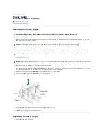
Page 6: ...Back to Contents Page ...

Page 7: ...of the procedures in this section follow the safety instructions in the Owner s Manual NOTICE Only a certified service technician should perform repairs on your computer Damage due to servicing that is not authorized by Dell is not covered by your warranty CAUTION Handle components and cards with care Do not touch the components or contacts on a card Hold a card by its edges or by its metal mounti...

Page 8: ...d the system board 6 Open the computer cover 7 Press the lever on the card retention arm and raise the retention arm 8 If you are installing a new card remove the filler bracket to create a card slot opening Then continue with step 10 9 If you are replacing a card that is already installed in the computer remove the card If necessary disconnect any cables connected to the card Grasp the card by it...

Page 9: ...o place securing the card s in the computer 13 Connect any cables that should be attached to the card See the documentation for the card for information about the card s cable connections 14 Close the computer cover reconnect the computer and devices to electrical outlets and turn them on 15 Install any drivers required for the card as described in the card documentation CAUTION Some network adapt...

Page 10: ...2 Ensure that your computer and attached devices are turned off If your computer and attached devices did not automatically turn off when you shut down your computer turn them off now 3 Disconnect any telephone or telecommunication lines from the computer 4 Disconnect your computer and all attached devices from their electrical outlets and then press the power button to ground the system board 5 O...

Page 11: ... tab fits into the notch on the front end of the card 3 Secure the card by lowering the hinged lever on the back panel 4 Close the computer cover 5 Connect the monitor cable to the card s video connector 6 Connect your computer and devices to electrical outlets and turn them on Back to Contents Page NOTICE To connect a network cable first plug the cable into the network wall jack and then plug it ...

Page 12: ... parts are left inside the computer 3 Close the cover a Pivot the cover down b Press down on the right side of the cover until it closes c Press down on the left side of the cover until it closes d Ensure that both sides of the cover are locked If not repeat all of step 3 4 Connect your computer and devices to electrical outlets and turn them on Back to Contents Page NOTICE To connect a network ca...

Page 13: ... computer press the release button on the right side of the computer with one hand while pulling up on the top of the cover with the other hand b Press the release button on the left side of the computer with one hand while pulling up on the top of the cover with the other hand c Hold the bottom of the computer with one hand and then pull open the cover with the other hand Back to Contents Page CA...

Page 14: ...ching an unpainted metal surface on the chassis such as the metal around the card slot openings at the back of the computer before touching anything inside your computer While you work periodically touch an unpainted metal surface on the computer chassis to dissipate any static electricity that might harm internal components 7 Open the computer cover Removing a Hard Drive 1 Disconnect the power an...

Page 15: ...rails attached remove the rails from the old drive by removing the two screws that secure each rail to the drive Attach the bracket rails to the new drive by aligning the screw holes on the drive with the screw holes on the bracket rails and then inserting and tightening all four screws two screws on each rail 4 Install the hard drive into the computer by gently sliding the drive into place until ...

Page 16: ...ch the rails to the hard drive using the two screws attached to the rails Ensure that the rail tabs are positioned at the back of the hard drive 9 Remove the first hard drive from the upper bay and install it in the lower bay a Disconnect the power and the hard drive cables from the back of the first hard drive b Press in the two green rail tabs and pull the first hard drive out of the upper bay N...

Page 17: ...ted to the middle connector is the slave device Be sure that the jumper setting on the new device is set for cable select see the documentation that came with the drive for information 13 Close the computer cover 14 Connect your computer and devices to electrical outlets and turn them on 15 See the documentation that came with the drive for instructions on installing any software required for driv...

Page 18: ...nd devices to electrical outlets and turn them on 8 After you turn on your computer press F2 when you are prompted to enter setup mode 9 Highlight Drive Configuration and press Enter 10 Use the left and right arrows to change Diskette Drive A from Not Installed to 3 5 inch 1 44 MB 11 Press Enter 12 Highlight Integrated Devices LegacySelect Options and press Enter 13 Make sure that the Diskette Int...

Page 19: ...touch an unpainted metal surface on the computer chassis to dissipate any static electricity that might harm internal components 6 Open the computer cover Removing a CD DVD Drive 1 Disconnect the power audio and CD DVD drive cables from the back of the drive 2 Press inward on the two tabs on the sides of the drive and then slide the drive upward and remove it from the drive bay CAUTION Before you ...

Page 20: ...e screw holes on the drive with the screw holes on the bracket rails and then inserting and tightening all four screws two screws on each rail 4 Gently slide the drive into place until the tabs securely click into position 5 Connect the power audio and CD DVD drive cables to the drive 6 If you are installing a new CD DVD drive rather than replacing a drive remove the front panel insert 7 If you ar...

Page 21: ...Remove the front panel door by gently snapping it off the two hinge arms Removing the Front Panel Insert Remove the front panel insert before you install the floppy drive 1 Open the computer cover to a 90 degree angle 2 Locate the insert that is in front of the drive bay that you want to use 3 From inside the computer press in the release tab of the insert CAUTION Before you begin any of the proce...

Page 22: ... insert away from the computer s front panel 5 Remove the insert from the insert frame by pressing on the four tabs 6 Reattach the empty insert frame over the front of the drive bay The insert frame fits only one way Back to Contents Page ...

Page 23: ...mory modules they function at the slowest speed of the modules you install l Be sure to install a single memory module in DIMM 1 or the connector closest to the processor before you install modules in the other connectors Addressing Memory with 4 GB Configurations Your computer supports a maximum of 4 GB of memory when you use four 1 GB DIMMs Current operating systems such as Microsoft Windows XP ...

Page 24: ...odule back and forth to remove it from the connector 8 To insert a module press out the securing clip at each end of the memory module connector 9 Align the notch on the bottom of the module with the crossbar in the connector 10 Insert the module straight down into the connector ensuring that it fits into the vertical guides at each end of the connector Press firmly on the ends of the module until...

Page 25: ...the Start button right click My Computer and then click Properties 14 Click the General tab 15 To verify that the memory is installed correctly check the amount of memory RAM listed Back to Contents Page NOTICE To connect a network cable first plug the cable into the network wall jack and then plug it into the computer ...

Page 26: ...or on the system board 8 Lift up the airflow shroud 9 Remove the heat sink a Release the retention module clip by pressing in on the tab and lifting the retention module clip up CAUTION Before you begin any of the procedures in this section follow the safety instructions in your Owner s Manual NOTICE To disconnect a network cable first unplug the cable from your computer and then unplug it from th...

Page 27: ... NOTICE Lay the heat sink down with the thermal grease facing upward NOTICE If you are installing a microprocessor upgrade kit from Dell discard the original heat sink If you are not installing a microprocessor upgrade kit from Dell reuse the original heat sink and blower when you install your new microprocessor NOTICE Be careful not to bend any of the pins when you remove the microprocessor from ...

Page 28: ...was sent 6 Install the heat sink a Insert the notched end of the heat sink onto the end of the retention base that is opposite the hinge b Lower the heat sink until it fits securely in the base NOTICE Ground yourself by touching an unpainted metal surface on the back of the computer NOTICE Be careful not to bend any of the pins when you unpack the microprocessor Bending the pins can permanently da...

Page 29: ... the cooling fan power cable to the FAN2 connector on the system board 9 Reconnect the power cable to the PWR connector on the system board 10 Close the computer cover 11 Connect your computer and devices to electrical outlets and turn them on Back to Contents Page NOTICE To connect a network cable first plug the cable into the network wall jack and then plug it into the computer ...

Page 30: ...Back to Contents Page Removing and Installing Parts Dell Dimension 8300 Series Service Manual Back to Contents Page Cards Memory Front Panel Drives Microprocessor System Board Power Supply Battery ...

Page 31: ...y when you replace them to prevent their being pinched or crimped 7 Remove the two screws that attach the power supply to the back of the computer frame 8 Press the release button located on the floor of the computer frame 9 Slide the power supply toward the front of the computer approximately 1 inch 10 Lift the power supply up and out of the computer Replacing the Power Supply 1 Slide the power s...

Page 32: ...the AC power cable to the connector 5 Run the cables underneath the clips and press the clips to close them over the cables 6 Close the computer cover 7 Connect your computer and devices to electrical outlets and turn them on Back to Contents Page NOTICE To connect a network cable first plug the cable into the network wall jack and then plug it into the computer ...

Page 33: ...rs that support Hyper Threading technology Memory Type DDR 333 or 400 non ECC Memory connectors four Memory capacities 128 256 512 MB and 1 GB non ECC Minimum memory 256 MB Maximum memory 4 GB NOTE See Addressing Memory with 4 GB Configurations for the amount of memory available to the operating system BIOS address F8000h Computer Information System chip set Intel 875P DMA channels eight Interrupt...

Page 34: ...h integrated sound capabilities System board connectors Primary IDE channel 40 pin connector on PCI local bus Secondary IDE channel 40 pin connector on PCI local bus Serial ATA drive two 7 pin connectors Floppy drive 34 pin connector Telephony ATAPI 4 pin connector CD Audio ATAPI 4 pin connector Fan 3 pin connector Controls and Lights Power control push button Power light green light on power butt...

Page 35: ... Operating 0 25 G at 3 to 200 Hz at 1 2 octave min Storage 0 5 G at 3 to 200 Hz at 1 2 octave min Maximum shock Operating bottom half sine pulse with a change in velocity of 50 8 cm sec 20 inches sec Storage 23 G faired square wave with a velocity change of 508 cm sec 200 inches sec Altitude Operating 15 2 to 3048 m 50 to 10 000 ft NOTE At 35ºC 95ºF the maximum operating altitude is 914 m 3000 ft ...

Page 36: ... the existing system board to make sure that you have the correct part 9 Pull up on the tab and slide the system board assembly toward the front of the computer and then lift it up and away 10 Place the system board assembly that you just removed next to the replacement system board Replacing the System Board CAUTION Before you begin any of the procedures in this section follow the safety instruct...

Page 37: ...toward the back of the computer until it clicks into place 6 Replace any components and cables that you removed from the system board 7 Reconnect all cables to their connectors at the back of the computer 8 Close the computer cover 9 Connect your computer and devices to electrical outlets and turn them on Back to Contents Page CAUTION The microprocessor package and heat sink assembly can get hot T...

Page 38: ...p program screen information for future reference Entering the System Setup Program Viewing Settings 1 Turn on or restart your computer 2 When the blue DELL logo appears press F2 immediately If you wait too long and the operating system logo appears continue to wait until you see the Microsoft Windows desktop Then shut down your computer and try again See the following figure for an example of the...

Page 39: ...ns when Enter is pressed System Security Displays system security options when Enter is pressed Keyboard Numlock Turns the Keyboard NumLock option on and off The default is On Report Keyboard Errors Displays keyboard errors when set to Report The default is Report Auto Power On Allows auto power on The default is Disabled Fast Boot Turns the fast boot option on and off The default is On OS Install...

Page 40: ...d Turns the integrated sound off and on The default is On Network Interface Controller Turns the network interface controller off and on The default is On Mouse Port Turns the mouse port off and on The default is On USB Emulation Turns USB emulation off and on The default is On USB Controller Turns the USB controller off and on The default is On Serial Port 1 Sets serial port options and turns the...

Page 41: ... menu 2 Turn off any attached devices and disconnect them from their electrical outlets 3 Disconnect the computer power cable from the wall outlet and then press the power button to ground the system board 4 Open the computer cover 5 Locate jumper PSWD on the system board and remove the jumper plug 6 Close the computer cover plug your computer into an electrical outlet and turn on the computer The...

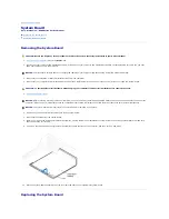
Page 42: ...Back to Contents Page ...

Page 43: ...ng Inside Your Computer System Board NOTE The AGP card is removed from the following illustration to provide a better view of the inside of your computer CAUTION Before you begin any of the procedures in this section follow the safety instructions listed in When Working Inside Your Computer in your Owner s Manual NOTICE Be careful when opening the computer cover to ensure that you do not inadverte...

Page 44: ...e of the ranges listed but within each specified output current range the 5 V 12 V and 3 3 V outputs are allowed to regulate at 10 of nominal DC voltages 1 Maximum continuous total DC output cannot exceed 200 W Maximum continuous combined load on 5 VDC and 3 3 VDC outputs cannot exceed 135 W 2 Peak 12 VDC output power up to 12 A does not exceed 15 seconds in duration In this condition the toleranc...

Page 45: ...3 VDC Orange 2 3 3 VDC Orange 3 COM Black 4 5 VDC Red 5 COM Black 6 5 VDC Red 7 COM Black 8 POK Gray 9 5 VFP Purple 10 12 VDC Yellow 11 3 3 VDC Orange 12 12 VDC Blue 13 COM Black 14 PS ON Green 15 COM Black 16 COM Black 17 COM Black 18 N C N C 19 5 VCD Red 20 5 VCD Red Sense connector ...

Page 46: ...2 VCD Yellow 2 COM Black 3 COM Black 4 5 VDC Red Pin Number Signal Name 22 AWG Wire 1 5 VCD Red 2 COM Black 3 COM Black 4 12 VDC Yellow IDE Channel Connector Location Dell Installed Drive Primary IDE master End connector on PRI IDE connector cable Hard drive Primary IDE slave Middle connector on PRI IDE connector cable Zip drive Secondary IDE master End connector on SEC IDE connector cable CD or D...

Page 47: ...k to Contents Page Card Connector Card Description AGP connector Video PCI1 connector Network adapter wireless network adapter or swap box PCI2 connector Modem PCI3 connector Sound PCI4 connector IEEE 1394 ...

Page 48: ...rademarks used in this text Dell the DELL logo and Dimension are trademarks of Dell Inc Intel and Pentium are registered trademarks of Intel Corporation Microsoft and Windows are registered trademarks of Microsoft Corporation Other trademarks and trade names may be used in this document to refer to either the entities claiming the marks and names or their products Dell Inc disclaims any proprietar...

Page 49: ...k the Start button and then click Turn Off Computer 2 In the Turn off computer window click Turn off The computer turns off after the shutdown process finishes Back to Contents Page NOTICE To avoid losing data turn off your computer by performing a Microsoft Windows operating system shutdown as described next rather than by pressing the power button ...

Reviews: