background image

Advanced Troubleshooting: Dell Dimension 9150 Service Manual

file:///T|/htdocs/systems/dim9150/en/sm/adtshoot.htm[10/31/2012 7:59:03 AM]

Back to Contents Page

 Advanced Troubleshooting

Dell™ Dimension™ 9150 Service Manual


Power Lights


Diagnostic Lights


Beep Codes

Power Lights

CAUTION: 

Before you begin any of the procedures in this section, follow the safety instructions in the

Product Information Guide.

The power button light located on the front of the computer illuminates and blinks or remains solid to indicate different states:

If the power light is green and the computer is not responding. 

Ensure the display is connected and powered on. 

If the display is connected and powered on, see "

Diagnostic Lights

".

If the power light is blinking green, the computer is in standby mode. Press a key on the keyboard, move the mouse,

or press the power button to resume normal operation.

If the power light is off, the computer is either turned off or is not receiving power.

Reseat the power cable into both the power connector on the back of the computer and the electrical outlet.

If the computer is plugged into a power strip, ensure that the power strip is plugged into an electrical outlet and

that the power strip is turned on. Also bypass power protection devices, power strips, and power extension

cables to verify that the computer turns on properly.

Ensure that the electrical outlet is working by testing it with another device, such as a lamp.

Ensure that the main power cable and front panel cable are securely connected to the system board.

If the power light is blinking amber, the computer is receiving electrical power, but an internal power problem might

exist.

Ensure that the voltage selection switch is set to match the AC power at your location (if applicable).

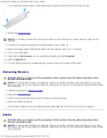
If the power light is steady amber, a device might be malfunctioning or incorrectly installed.

Remove and then reinstall the 

memory modules

.

Remove and then reinstall any 

cards

.

Remove and then reinstall the 

graphics card

, if applicable.

Ensure that all power cables are securely connected to the system board.
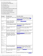
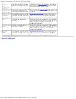
Diagnostic Lights

CAUTION: 

Before you begin any of the procedures in this section, follow the safety instructions in the

Product Information Guide.

Summary of Contents for Dimension 9150

Page 1: ...or death If you purchased a Dell n Series computer any references in this document to Microsoft Windows operating systems are not applicable Information in this document is subject to change without notice 2006 Dell Inc All rights reserved Reproduction in any manner whatsoever without the written permission of Dell Inc is strictly forbidden Trademarks used in this text Dell the DELL logo and Dimen...

Page 2: ...performing the removal procedure in reverse order Recommended Tools The procedures in this document may require the following tools Small flat blade screwdriver Phillips screwdriver Long Phillips screwdriver Flash BIOS update program floppy disk or CD Turning Off Your Computer NOTICE To avoid losing data save and close any open files and exit any open programs before you turn off your computer 1 S...

Page 3: ...e cables have a connector with locking tabs if you are disconnecting this type of cable press in on the locking tabs before you disconnect the cable As you pull connectors apart keep them evenly aligned to avoid bending any connector pins Also before you connect a cable ensure that both connectors are correctly oriented and aligned NOTICE To avoid damaging the computer perform the following steps ...

Page 4: ...1 cover latch release Use this latch to remove the cover See Removing the Computer Cover 2 CD or DVD activity light The drive light is on when the computer reads data from the CD or DVD drive 3 CD or DVD eject button Press to eject a disc from the CD or DVD drive 4 Floppy drive bay Can contain an optional floppy drive 5 FlexBay Can contain an optional floppy drive or optional Media Card Reader 6 I...

Page 5: ...unction properly if attached to the front connectors 9 power button Press to turn on the computer NOTICE To avoid losing data do not use the power button to turn off the computer Instead perform an operating system shutdown 10 hard drive activity light The hard drive activity light is on when the computer reads data from or writes data to the hard drive The light might also be on when a device suc...

Page 6: ...kers 3 network connector To attach your computer to a network or broadband device connect one end of a network cable to either a network port or your network or broadband device Connect the other end of the network cable to the network connector on your computer A click indicates that the network cable has been securely attached NOTE Do not plug a telephone cable into the network connector On comp...

Page 7: ...About Your Computer Dell Dimension 9150 Service Manual file T htdocs systems dim9150 en sm about htm 10 31 2012 7 58 47 AM ...

Page 8: ...nted metal surface such as the metal at the back of the computer While you work periodically touch an unpainted metal surface to dissipate any static electricity that could harm internal components 1 Follow the procedures in Before You Begin 2 If you have installed a security cable remove it from the security cable slot NOTICE Ensure that sufficient space exists to support the removed cover at lea...

Page 9: ...ension 9150 Service Manual file T htdocs systems dim9150 en sm cvrop htm 10 31 2012 7 58 49 AM 6 Grip the sides of the computer cover and pivot the cover up 7 Lift the cover away and set it aside in a secure location Back to Contents Page ...

Page 10: ...nts Page Technical Overview Dell Dimension 9150 Service Manual Inside View of Your Computer System Board Components Power Supply DC Connector Pin Assignments Inside View of Your Computer CAUTION Before you begin any of the procedures in this section follow the safety instructions in the Product Information Guide System Board Components ...

Page 11: ...Technical Overview Dell Dimension 9150 Service Manual file T htdocs systems dim9150 en sm techov htm 10 31 2012 7 58 55 AM Power Supply DC Connector Pin Assignments ...

Page 12: ... en sm techov htm 10 31 2012 7 58 55 AM DC Power Connector P1 Pin Number Signal Name Color Wire Gauge 1 3 3 VDC Orange 18 AWG 2 3 3 VDC Orange 18 AWG 3 COM Black 18 AWG 4 5 VDC Red 18 AWG 5 COM Black 18 AWG 6 5 VDC Red 18 AWG 7 COM Black 18 AWG 8 POK Gray 18 AWG 9 5 VFP Purple 18 AWG ...

Page 13: ... Blue 18 AWG 15 COM Black 18 AWG 16 PS ON Green 18 AWG 17 COM Black 18 AWG 18 COM Black 18 AWG 19 COM Black 18 AWG 20 N C N C 18 AWG 21 5 VDC Red 18 AWG 22 5 VDC Red 18 AWG 23 5 VDC Red 18 AWG 24 COM Black 18 AWG DC Power Connector P2 Pin Number Signal Name 18 AWG Wire 1 COM Black 2 COM Black 3 12 VA DC Yellow 4 12 VA DC Yellow DC Power Connect P3 and P5 Pin Number Signal Name 18 AWG Wire 1 3 3 VD...

Page 14: ... DC White DC Power Connector P4 Pin Number Signal Name 18 AWG Wire 1 N C N C 2 COM Black 3 COM Black 4 3 3 VDC Orange 5 5 VDC Red 6 12A VDC Yellow DC Power Connector P7 Pin Number Signal Name 18 AWG Wire 1 5 VDC Red 2 COM Black 3 COM Black 4 12 A VDC Yellow DC Power Connectors P8 P9 and P10 Pin Number Signal Name 18 AWG Wire 1 12 VA DC Yellow ...

Page 15: ...or is intended for use with PCI Express graphics cards that have power requirements exceeding 75 watts DC Power Connector P11 Pin Number Signal Name 18 AWG Wire 1 12 VB DC White 2 COM Black 3 COM Black 4 5V DC Red DC Power Connector P12 Pin Number Signal Name 18 AWG Wire 1 12 B VDC White 2 12 B VDC White 3 12 B VDC White 4 COM Black 5 COM Black 6 COM Black Back to Contents Page ...

Page 16: ...our Memory capacities 256 MB 512 MB or 1 GB Minimum memory 512 MB Maximum memory 4 GB BIOS address F0000h Computer Information Chipset Intel 945P DMA channels eight Interrupt levels 24 BIOS chip NVRAM 4 Mb NIC integrated network interface capable of 10 100 1000 Mbps communication System clock 800 or 1066 MHz data rate Video Type PCI Express Audio Type internal 7 1 channel or PCI option cards Expan...

Page 17: ...ze 164 pins connector data width maximum 16 PCI Express lanes Drives Externally accessible two 3 5 inch drive bays FlexBay two 5 25 inch drive bays Available devices serial ATA drives 2 floppy drive USB memory devices CD drive CD RW drive DVD drive DVD RW drive Media Card Reader and DVD CD RW combo drive Internally accessible two 3 5 inch hard drive bays Connectors External connectors IEEE 1394 on...

Page 18: ...with the power supply inside the computer If the system cannot boot and there is a solid amber light this indicates a problem with the system board see Power Lights Hard drive access light green Link integrity light on integrated network adapter green light A good connection exists between a 10 Mbps network and the computer orange light A good connection exists between a 100 Mbps network and the c...

Page 19: ... Weight 15 4 kg 34 lb Environmental Temperature Operating 10 to 35 C 50 to 95 F Storage 40 to 65 C 40 to 149 F Relative humidity 20 to 80 noncondensing Maximum vibration Operating 0 25 G at 3 to 200 Hz at 0 5 octave min Storage 0 5 G at 3 to 200 Hz at 1 octave min Maximum shock Operating bottom half sine pulse with a change in velocity of 20 inches sec 50 8 cm sec Storage 27 G faired square wave w...

Page 20: ...nnector on the back of the computer and the electrical outlet If the computer is plugged into a power strip ensure that the power strip is plugged into an electrical outlet and that the power strip is turned on Also bypass power protection devices power strips and power extension cables to verify that the computer turns on properly Ensure that the electrical outlet is working by testing it with an...

Page 21: ... Cards reinstall it and then restart the computer If the problem still exists install a graphics card that you know works and restart the computer If the problem persists contact Dell A possible floppy drive or hard drive failure has occurred Reseat all power and data cables and restart the computer A possible USB failure has occurred Reinstall all USB devices check cable connections and then rest...

Page 22: ...le beep code code 1 3 1 consists of one beep a burst of three beeps and then one beep This beep code tells you that the computer encountered a memory problem Reseating the memory modules may fix the beep code errors in the following table If the problem persists see Contacting Dell in your Owner s Manual for instructions on obtaining technical assistance Code Cause 1 3 1 through 2 4 4 Memory not b...

Page 23: ...orrectly in the system setup program Cache Memory Bad Do Not Enable Cache The cache memory is not operating See Contacting Dell in your Owner s Manual for instructions on obtaining technical assistance CH 2 Timer Error An error is occurring on the timer on the system board See Contacting Dell in your Owner s Manual for instructions on obtaining technical assistance CMOS Battery State Low CMOS Chec...

Page 24: ...located on drive A or drive C Enter the system setup program and confirm that drive A or drive C is properly identified Keyboard Error The BIOS has detected a stuck key Ensure that nothing is resting on the keyboard if a key appears to be stuck carefully pry it up If the problem persists you may need to replace the keyboard KB Interface Error An error occurred with the keyboard connector Ensure th...

Page 25: ...this F2 prompt appears press F2 immediately NOTE The F2 prompt indicates that the keyboard has initialized This prompt can appear very quickly so you must watch for it to display and then press F2 If you press F2 before you are prompted this keystroke will be lost 4 If you wait too long and the operating system logo appears continue to wait until you see the Microsoft Windows desktop Then shut dow...

Page 26: ...so displays a table that describes the memory size whether the memory module is ECC capable single or dual rank type and organization PCI Info Displays the contents of each PCI slot Date Time Controls the system s internal calendar and clock Boot Sequence Determines the order in which the system searches for boot devices during system startup NOTE If you insert a boot device and restart the comput...

Page 27: ...oller is installed in a 64 bit PCIx expansion slot Performance Multiple CPU Core This setting specifies whether more than one core is enabled The performance of some applications may improve with an additional core enabled The default is On second core enabled SpeedStep If applicable Intel SpeedStep appears in the Options List under Performance HyperThreading If your computer processor supports Hy...

Page 28: ... is selected this setting restores the computer s default settings The default setting is Cancel Event Log Displays the system event log POST Behavior Fastboot When set to On default your computer starts more quickly because it skips certain configurations and tests Numlock Key This option involves the rightmost bank of keys on your keyboard When set to On default this option activates the numeric...

Page 29: ...he operating system logo appears continue to wait until you see the Microsoft Windows desktop Then shut down your computer and try again The Boot Device Menu appears listing all available boot devices Each device has a number next to it 4 At the bottom of the menu enter the number of the device that is to be used for the current boot only For example if you are booting to a USB memory key highligh...

Page 30: ...electrical outlet 8 Disconnect the computer power cable from the electrical outlet and press the power button to ground the system board 9 Open the computer cover 10 Reattach the password jumper PSWD to pins 1 and 2 to re enable the password feature 11 Replace the computer cover NOTICE To connect a network cable first plug the cable into the network port or device and then plug it into the compute...

Page 31: ...s b Remove the jumper plug from pins 1 and 2 c Place the jumper plug on pins 2 and 3 and wait approximately five seconds d Replace the jumper plug on pins 1 and 2 3 Replace the computer cover NOTICE To connect a network cable first plug the cable into the network port or device and then plug it into the computer 4 Connect your computer and devices to electrical outlets and turn them on Back to Con...

Page 32: ...pport dell com Memory Overview Memory modules should be installed in pairs of matched memory size speed and technology If the memory modules are not installed in matched pairs the computer will continue to operate but with a slight reduction in performance See the label in the corner of the module to determine the module s capacity NOTE Always install memory modules in the order indicated on the s...

Page 33: ...y With 4 GB Configurations Your computer supports a maximum of 4 GB of memory when you use four 1 GB DIMMs Current operating systems such as Microsoft Windows XP can only use a maximum of 4 GB of address space however the amount of memory available to the operating system is less than 4 GB Certain components within the computer require address space in the 4 GB range Any address space reserved for...

Page 34: ...012 7 59 36 AM 5 Align the notch on the bottom of the module with the crossbar in the connector NOTICE To avoid damage to the memory module press the module straight down into the connector while you apply equal force to each end of the module 6 Insert the module into the connector until the module snaps into position ...

Page 35: ...egin any of the procedures in this section follow the safety instructions in the Product Information Guide NOTICE To prevent static damage to components inside your computer discharge static electricity from your body before you touch any of your computer s electronic components You can do so by touching an unpainted metal surface on the computer 1 Follow the procedures in Before You Begin 2 Remov...

Page 36: ...One PCI Express x1 card slot One PCI Express x16 card slot One PCI Express x4 card slot Removing and Installing PCI and PCI Express Cards NOTE Dell offers an optional customer kit for Audigy II and IEEE 1394 PCI add in cards that includes a front mounted IEEE 1394 connector 1 If you are replacing a card remove the current driver for the card from the operating system 2 Follow the procedures in Bef...

Page 37: ...the open position 5 If your computer includes a card retention mechanism a Grasp the end of the card retention mechanism and while pressing the release tab down with your thumb rotate the mechanism towards the base of the computer b Detach the mechanism from its retaining tabs and set it aside in a secure location 6 If a piano bracket for full length PCI E cards is present on your computer rotate ...

Page 38: ...rd remove the filler bracket to create a card slot opening 9 Prepare the card for installation See the documentation that came with the card for information on configuring the card making internal connections or otherwise customizing it for your computer CAUTION Some network adapters automatically start the computer when they are connected to a network To guard against electrical shock be sure to ...

Page 39: ...ller bracket fits around the alignment guide 13 Close the card retention door by snapping it into place to secure the card s NOTICE Do not route card cables over or behind the cards Cables routed over the cards can prevent the computer cover from closing properly or cause damage to the equipment 14 If you installed a card connect any cables that should be attached to the card See the documentation...

Page 40: ... the operating system b If you installed a card install any drivers required for the card as described in the card documentation Network Adapter and Sound Card Settings If you installed a sound card 1 Enter system setup select Integrated Audio Controller and then change the setting to Off 2 Connect external audio devices to the sound card connectors Do not connect external audio devices to the mic...

Page 41: ...es in this section follow the safety instructions in the Product Information Guide CAUTION To guard against electrical shock always unplug your computer from the electrical outlet before removing the cover Removing the Drive Panel 1 Follow the procedures in Before You Begin 2 Grasping the lever on the sliding plate pull the sliding plate to the right and hold in place NOTE The sliding plate secure...

Page 42: ...approximately 1 cm inch away from the drive panel before sliding the tab out of the slot 1 On the inside of the drive panel pinch the two drive panel insert release tabs together and pull the insert out and to the right just enough to release it from the drive panel 2 Set the drive panel insert aside in a secure location Replacing the Drive Panel Insert 1 Place the drive panel insert tab into the ...

Page 43: ...d the computer until the sliding plate lever clicks into place and the drive panel snaps into place on the front panel Drives Your computer supports Two hard drives Serial ATA One floppy drive One flexbay drive Two CD or DVD drives Connecting Drive Cables When you install a drive you connect two cables a DC power cable and a data cable to the back of the drive and to the system board Some CD DVD d...

Page 44: ...at the pin 1 wire in the cable indicated by the colored stripe along one edge of the IDE cable serial ATA cables do not use a colored stripe goes to the pin 1 end of the connector The pin 1 end of a connector on a board or a card is usually indicated by a silk screened 1 printed directly on the board or card NOTICE When you connect an IDE interface cable do not place the colored stripe away from p...

Page 45: ...e do not set it on a hard surface Instead set the drive on a surface such as a foam pad that will sufficiently cushion it 1 If you are replacing a hard drive that contains data you want to keep back up your files before you begin this procedure 2 Follow the procedures in Before You Begin 3 Remove the computer cover Removing a Hard Drive 1 Disconnect the power and SATA data cables from the drive 2 ...

Page 46: ...bracket from the old hard drive by unsnapping it from the drive 4 Snap the hard drive bracket onto the replacement hard drive 5 Install the hard drive into the computer by sliding the drive into place until you feel it click into place 6 Connect the power and SATA data cables to the hard drive 7 Check all connectors to be certain that they are properly cabled and firmly seated 8 Replace the comput...

Page 47: ...procedures in this section follow the safety instructions in the Product Information Guide CAUTION To guard against electrical shock always unplug your computer from the electrical outlet before opening the cover NOTICE To avoid damage to the drive do not set it on a hard surface Instead set the drive on a surface such as a foam pad that will sufficiently cushion it 1 Check the documentation for t...

Page 48: ...ter cover NOTICE To connect a network cable first plug the cable into the network port or device and then plug it into the computer 10 Connect your computer and devices to electrical outlets and turn them on See the documentation that came with the drive for instructions on installing any software required for drive operation Floppy Drive CAUTION Before you begin any of the procedures in this sect...

Page 49: ...lling a Floppy Drive Removing a Floppy Drive 1 Follow the procedures in Before You Begin 2 Remove the computer cover 3 Disconnect the power and floppy drive cables from the back of the floppy drive 4 Disconnect the other end of the floppy drive cable from the system board 5 Pull the sliding plate to the right and hold in place 6 Slide the floppy drive out of the floppy drive bay ...

Page 50: ...t plug the cable in to the network port or device and then plug it in to the computer 7 Connect your computer and devices to their electrical outlets and turn them on See the documentation that came with the floppy drive for instructions on installing any software required for the operation of the drive 8 Enter system setup and select the appropriate Diskette Drive option 9 Verify that your comput...

Page 51: ...e drive panel 5 Disconnect the USB cable on the back of the Media Card Reader from the front panel USB connector on the system board see System Board Components and remove the cable from the clip on the shroud 6 While pushing on the back of the drive remove the Media Card Reader by sliding and holding the sliding plate 7 Replace the drive panel ...

Page 52: ... do so by touching an unpainted metal surface on the computer chassis 1 Follow the procedures in Before You Begin 2 Lay the computer on its side so that the system board is on the bottom of the inside of the computer 3 Remove the computer cover 4 Remove the drive panel 5 Remove the Media Card Reader from its packaging and ensure that all four screws are included 6 Gently slide the drive into place...

Page 53: ...puter cover CD DVD Drive CAUTION Before you begin any of the procedures in this section follow the safety instructions in the Product Information Guide CAUTION To guard against electrical shock always unplug your computer from the electrical outlet before opening the cover Removing a CD DVD Drive 1 Follow the procedures in Before You Begin 2 Remove the computer cover 3 Disconnect the power cable f...

Page 54: ...rive bay Installing a CD DVD Drive 1 If you are installing a new drive unpack the drive and prepare it for installation Check the documentation that accompanied the drive to verify that the drive is configured for your computer If you are installing an IDE drive configure the drive for the cable select setting 2 If you are installing a new drive remove the three shoulder screws from the inside of ...

Page 55: ... 6 Check all cable connections and fold cables out of the way to provide airflow for the fan and cooling vents 7 Replace the computer cover NOTICE To connect a network cable first plug the cable in to the network port or device and then plug it in to the computer 8 Connect your computer and devices to their electrical outlets and turn them on See the documentation that came with the drive for inst...

Page 56: ...the DC power cables underneath the tabs in the computer frame as you remove them from the system board and drives You must route these cables properly when you replace them to prevent them from being pinched or crimped 3 Remove any cables from the cable routing clip on the power supply 4 Remove the four screws that attach the power supply to the back of the computer frame 5 Press the release butto...

Page 57: ...e clips to close them over the cables 6 Replace the computer cover NOTICE To connect a network cable first plug the cable into the network port or device and then plug the cable into the computer 7 Connect your computer and devices to electrical outlets and turn them on Processor CAUTION Before you begin any of the procedures in this section follow the safety instructions in the Product Informatio...

Page 58: ...plastic shield the heat sink assembly may be very hot during normal operation Be sure that it has had sufficient time to cool before you touch it 5 Rotate the heat sink assembly toward the rear of the computer and remove it from the computer 1 heat sink and fan shroud assembly 2 captive screw housing 2 NOTICE If you are installing a processor upgrade kit from Dell discard the original heat sink If...

Page 59: ... not touch any of the pins inside the socket or allow any objects to fall on the pins in the socket 8 Gently remove the processor from the socket Leave the release lever extended in the release position so that the socket is ready for the new processor Installing the Processor NOTICE Ground yourself by touching an unpainted metal surface on the back of the computer NOTICE When replacing the proces...

Page 60: ...e socket and ensure that the processor is positioned correctly 6 When the processor is fully seated in the socket close the processor cover Ensure that the securing tab on the processor cover is positioned underneath the center cover latch on the socket 7 Pivot the socket release lever back toward the socket and snap it into place beneath the securing tab NOTICE If you are not installing a process...

Page 61: ...e computer cover NOTICE To connect a network cable first plug the cable into the network port or device and then plug the cable into the computer 10 Connect your computer and devices to electrical outlets and turn them on I O Panel CAUTION Before you begin any of the procedures in this section follow the safety instructions in the Product Information Guide CAUTION To guard against electrical shock...

Page 62: ...rk lights 3 headphones connector 4 microphone connector Removing the I O Panel 1 Follow the procedures in Before You Begin 2 Remove the computer cover 3 If your computer includes a card retention mechanism to secure the x16 card in place from the top a Pivot the mechanism upward and gently press the release tab downward to release the mechanism from the two tab slots holding it in place ...

Page 63: ...plastic shield the heat sink assembly may be very hot during normal operation Be sure that it has had sufficient time to cool before you touch it 5 Rotate the heat sink assembly towards the rear of the computer and remove it from the computer 1 heat sink and fan shroud assembly 2 captive screw housing 2 6 Place the heat sink assembly on its side in a safe place 7 Disconnect the system fan cable fr...

Page 64: ...e it from the bottom cover 10 Remove the fan from the computer 11 Disconnect the control panel cable from the I O panel connector by pulling with the cable loop 12 Remove the drive panel 13 If an optional sound card is installed disconnect the cable from the edge of the I O panel 14 If an optional IEEE 1394 cable is installed in the front port remove the cable from the front of the computer by fol...

Page 65: ...ctricity from your body before you touch any of your computer s electronic components You can do so by touching an unpainted metal surface on the computer A coin cell battery maintains computer configuration date and time information The battery can last several years If you have to repeatedly reset time and date information after you have turned on the computer replace the battery CAUTION A new b...

Page 66: ...new battery into the socket with the side labeled facing up and snap the battery into place 7 Replace the computer cover NOTICE To connect a network cable first plug the cable into the network port or device and then plug it into the computer 8 Connect your computer and devices to electrical outlets and turn them on 9 Enter system setup and restore the settings you recorded in step 1 CAUTION For i...

Page 67: ...d all attached devices from their electrical outlets and then press the power button to ground the system board 5 Open the computer cover 6 Remove any components that restrict access to the system board CD DVD drive s floppy drive hard drive I O panel 7 Remove the heat sink assembly and processor 8 Disconnect all cables from the system board 1 system board 2 screws 10 9 Remove the 10 screws from t...

Page 68: ...6 AM 4 Reconnect all cables to their connectors at the back of the computer 5 Replace the computer cover NOTICE To connect a network cable first plug the cable into the network port or device and then plug the cable into the computer 6 Connect your computer and devices to electrical outlets and turn them on Back to Contents Page ...

Page 69: ...t of the way Gently pull the power cables toward you so that they do not get caught underneath the drives 2 Ensure that no tools or extra parts are left inside the computer 3 Close the cover a Pivot the cover down b Press down on the right side of the cover until it closes c Press down on the left side of the cover until it closes d Ensure that both sides of the cover are locked If not repeat all ...

Reviews: