

Upgrade Kits
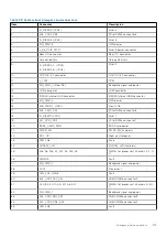
The table lists the available After Point Of Sale [APOS] kits.
Table 31. Upgrade kits
Kits
Part number
Related links to service instructions
Bezel
JYPW8/MPW3H (LCD)
Boss
BOSS S2
Installing the BOSS S2 controller card module
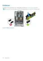
Embedded management (IDSDM)
C2KCJ
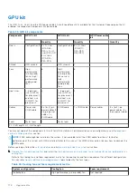
GPU
Accelerator enablement kit
Hard drives
Hard drives SSD
Installing the drive into the carrier
Memory
Network cards (Standard PCIe
adapter LP/FH)
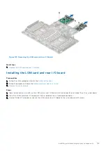
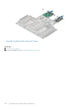
Installing the LOM card and rear I/O board
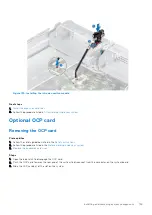
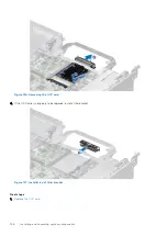
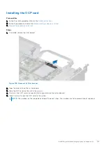
Network cards (OCP)
PCIe SSD card
Installing an expansion card into the expansion card riser
Power cords
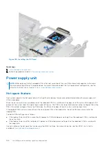
Power supplies
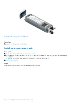
Installing a power supply unit
Quick sync
C70VC (PE) / 8XK5Y
(OEM)
SD cards
TPM
JD9CH
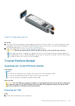
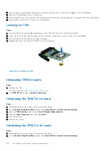
Upgrading the Trusted Platform Module
Processor enablement thermal kits TVMK2/C82YT/8T3V2/
JWDV5/NP3NR
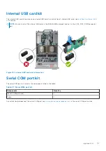
Internal USB 3.0 card
C19XC
Serial COM port daughter card
626YT
Installing the serial COM port
Topics:
•
•
•
•
•
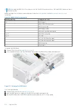
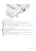
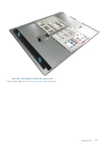
BOSS S2 kit
The BOSS S2 supports up to two M.2 SSDs.
5
Upgrade Kits
169


