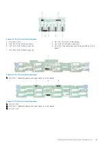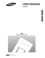
Figure 62. 16 x 2.5-inch drive backplane
1. BP_DST_SB1 (backplane to front PERC)
2. BP_PWR_1 (backplane power and signal cable to system
board)
3. BP_PWR_CTRL (front PERC power and control signal)
4. BP_DST_SA1 (backplane to front PERC)
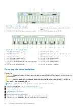
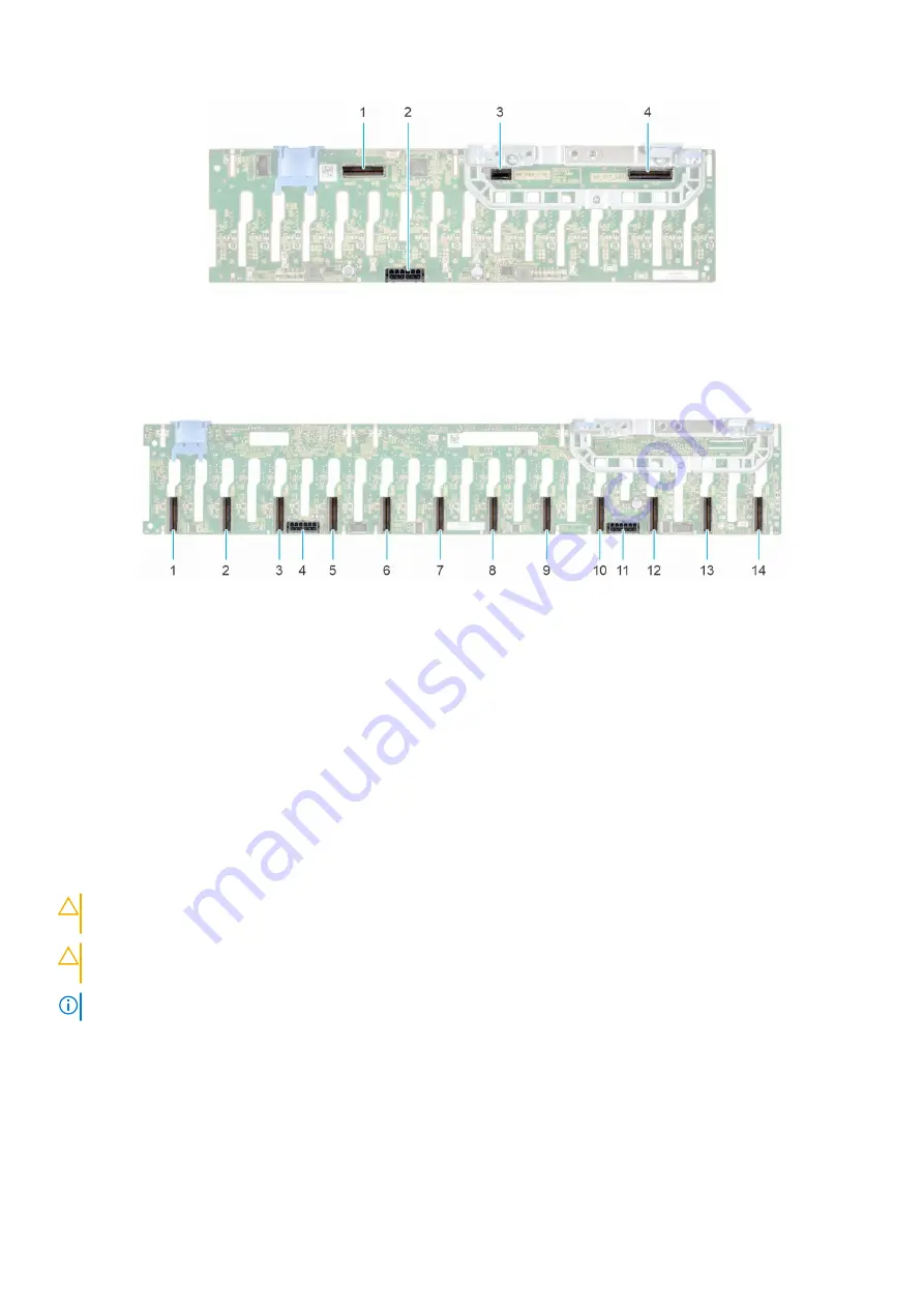
Figure 63. 24 x 2.5-inch drive backplane
1. DST_PB6 (PCIe/NVMe connector)
2. DST_PA6 (PCIe/NVMe connector)
3. DST_PB5 (PCIe/NVMe connector)
4. DST_PWR_2 (backplane power and signal cable to system
board)
5. DST_PA5 (PCIe/NVMe connector)
6. DST_PB4 (PCIe/NVMe connector)
7. DST_PA4 (PCIe/NVMe connector)
8. DST_PB3 (PCIe/NVMe connector)
9. DST_PA3 (PCIe/NVMe connector)
10. DST_PB2 (PCIe/NVMe connector)
11. DST_PWR_1 (backplane power and signal cable to system
board)
12. DST_PA2 (PCIe/NVMe connector)
13. DST_PB1 (PCIe/NVMe connector)
14. DST_PA1 (PCIe/NVMe connector)
Removing the drive backplane
Prerequisites
CAUTION:
To prevent damage to the drives and backplane, remove the drives from the system before removing
the backplane.
CAUTION:
Note the number of each drive and temporarily label them before you remove the drive so that you
can reinstall them in the same location.
NOTE:
The procedure to remove the backplane is similar for all backplane configurations.
1. Follow the safety guidelines listed in the
.
2. Follow the procedure listed in the
Before working inside your system
3.
4. If installed,
5.
.
6.
Remove the cooling fan cage assembly
.
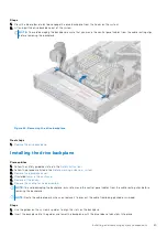
7. Disconnect the drive backplane cables from the connector on the system board.
8. Disconnect the drive backplane cables from the connector on the backplane.
64
Installing and removing system components

