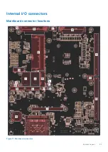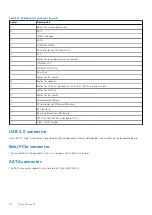
Table 17. Mainboard connector legend
Letter
Description
A
Smart fan (future expansion)
B
SATA
C
USB 2.0 dongle
D
SATA
E
DDR4 SO-DIMM
F
PCIe x16 slot for PEG and SATA
G
M.2
H
Wafer for reserved power of extensions
I
USIM for M.2
J
USIM for Mini PCIe
K
Mini PCIe
L
Wafer for I2C sensor
M
Wafer for speaker
N
Wafer for COM x2 (optional), 8-ch DI, 8-ch DO, mic in and line out
O
Wafer for COM x4
P
Wafer for I2C sensor
Q
Internal power button
R
PCIe x16 slot for PCIe and BP power
S
RTC battery
T
Board-to-Board for AFM board
U
PWR for AFM MXM carrier board (12 V)
V
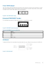
Clear CMOS Jumper
USB 2.0 connector
One USB 2.0 Type-A connector is provided on the mainboard for internal USB dongle, with another on the backplane board.
Mini PCIe connector
The internal Mini PCIe connector (Rev. 1.2) supports full-size Mini PCIe cards.
SATA connector
The SATA connector supports transfer up to 6.0 Gb/s (600 MB/s).
22
System Layout
Summary of Contents for EGW-5200
Page 1: ...Dell EMC Edge Gateway 5200 User s Guide January 2022 Rev A01 ...
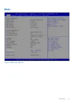
Page 31: ...Main Figure 27 BIOS screen Main tab BIOS Setup 31 ...
Page 32: ...Advanced Figure 28 BIOS screen Advanced tab 32 BIOS Setup ...
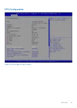
Page 33: ...CPU Configuration Figure 29 CPU Configuration top of screen BIOS Setup 33 ...
Page 47: ...NVMe Configuration Figure 41 NVMe Configuration BIOS Setup 47 ...
Page 51: ...Memory Configuration Figure 45 Memory Configuration BIOS Setup 51 ...
Page 54: ...PCH IO Configuration Figure 48 PCH IO Configuration 54 BIOS Setup ...
Page 56: ...Security Configuration Figure 50 Security Configuration 56 BIOS Setup ...
Page 57: ...M 2 Device Configuration Figure 51 M 2 Device Configuration BIOS Setup 57 ...
Page 58: ...Security Figure 52 BIOS screen Security tab 58 BIOS Setup ...
Page 64: ...Save and Exit Figure 57 BIOS screen Save and Exit tab 64 BIOS Setup ...
Page 65: ...Event logs Figure 58 BIOS screen Event logs tab BIOS Setup 65 ...

