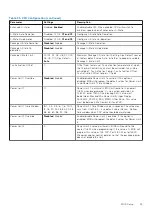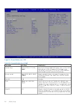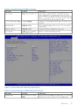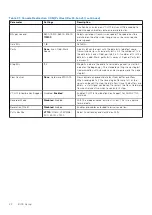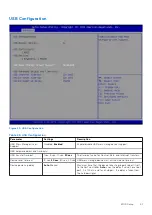
Table 27. Console Redirection COM(Pci Bus0,Dev22,Func3) (continued)
Parameter
Settings
Description
function keys, and so on. VT-UTF8: Uses UTF8 encoding to
map Unicode characters onto one or more bytes.
Bits per second
9600, 19200, 38400, 57600,
115200
Selects serial port transmission speed. The speed must be
matched on the other side. Long or noisy lines may require
lower speeds.
Data Bits
7,
8
Data Bits.
Parity
None
, Even, Odd, Mark,
Space
A parity bit can be sent with the data bits to detect some
transmission errors. Even: parity bit is 0 if the number of 1s in
the data bits is even. Odd: parity bit is 0 if number of 1s in the
data bits is odd. Mark: parity bit is always 1. Space: Parity bit
is always 0.
Stop Bits
1
, 2
Stop bits indicate the end of a serial data packet (a start bit
indicates the beginning). The standard setting is one stop bit.
Communication with slow devices may require more than one
stop bit.
Flow Control
None
, Hardware RTS/CTS
Flow control can prevent data loss from buffer overflow.
When sending data, if the receiving buffers are full, a stop
signal can be sent to stop the data flow. Once the buffers are
empty, a start signal can be sent to restart the flow. Hardware
flow control uses two wires to send start/stop.
VT-UTF8 Combo Key Support Disabled,
Enabled
Enable VT-UTF8 Combination Key Support for ANSI/VT100
terminals.
Recorder Mode
Disabled
, Enabled
With this mode enabled, only text is sent. This is to capture
terminal data.
Resolution 100x31
Disabled
, Enabled
Enables or disables extended terminal resolution.
Putty KeyPad
VT100
, LINUX, XTERMR6,
SCO, ESCN, VT400
Select FunctionKey and KeyPad on Putty.
40
BIOS Setup
Summary of Contents for EGW-5200
Page 1: ...Dell EMC Edge Gateway 5200 User s Guide January 2022 Rev A01 ...
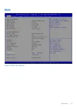
Page 31: ...Main Figure 27 BIOS screen Main tab BIOS Setup 31 ...
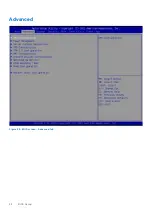
Page 32: ...Advanced Figure 28 BIOS screen Advanced tab 32 BIOS Setup ...
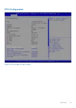
Page 33: ...CPU Configuration Figure 29 CPU Configuration top of screen BIOS Setup 33 ...
Page 47: ...NVMe Configuration Figure 41 NVMe Configuration BIOS Setup 47 ...
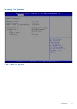
Page 51: ...Memory Configuration Figure 45 Memory Configuration BIOS Setup 51 ...
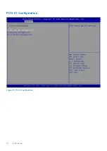
Page 54: ...PCH IO Configuration Figure 48 PCH IO Configuration 54 BIOS Setup ...
Page 56: ...Security Configuration Figure 50 Security Configuration 56 BIOS Setup ...
Page 57: ...M 2 Device Configuration Figure 51 M 2 Device Configuration BIOS Setup 57 ...
Page 58: ...Security Figure 52 BIOS screen Security tab 58 BIOS Setup ...
Page 64: ...Save and Exit Figure 57 BIOS screen Save and Exit tab 64 BIOS Setup ...
Page 65: ...Event logs Figure 58 BIOS screen Event logs tab BIOS Setup 65 ...

