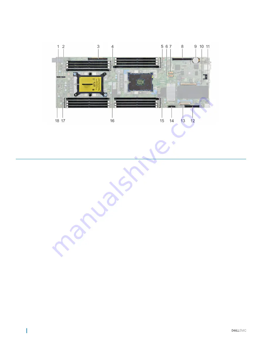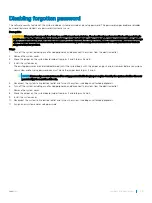
System board connectors
Figure 64. PowerEdge C6420 system board connectors
Table 36. System Board Connectors and Description
Item
Connector
Description
1
PCIe B
NVMe B connector
2
PCIe A
NVMe A connector
3
PCIe Slot 5
Slot 5: x16 PCIe Gen3 from CPU 2
4
DIMM sockets (4)
DIMM B8, DIMM B4, DIMM B5, DIMM B6
5
DIMM sockets (4)
DIMM A8, DIMM A4, DIMM A5, DIMM A6
6
HFI_SB_1
Side band cable 1 for OCP
7
HFI_SB_2
Side band cable 2 for OCP
8
PCIe Slot 4
Slot 4: x16 PCIe Gen3 CPU 1
9
Batt
System battery
10
PCIe Slot 3
Slot 3: x8 PCIe Gen3 from CPU 1
11
TPM
TPM connector
12
PCIe Slot 1
Slot 1: x8 PCIe Gen3 from CPU 1
13
PCIe Slot 2
Slot 2: x8 PCIe Gen3 from CPU 1
14
SATA_A
SATA cable connector
15
DIMM sockets (4)
DIMM A7, DIMM A1, DIMM A2, DIMM A3
16
CPU 1
CPU socket 1
17
DIMM sockets (4)
DIMM B7, DIMM B1, DIMM B2, DIMM B3
18
CPU 2
CPU socket 2 (with a dust cover)
124
Jumpers and connectors
Summary of Contents for EMC PowerEdge C6420
Page 1: ...Dell EMC PowerEdge C6420 Regulatory Model E43S Series Regulatory Type E43S001 ...
Page 8: ...Figure 1 Supported configurations for PowerEdge C6420 8 PowerEdge C6420 overview ...
Page 64: ...Figure 12 Removing a sled 64 Installing and removing system components ...
Page 66: ...Figure 14 Installing a sled 66 Installing and removing system components ...


