


Steps
1
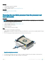
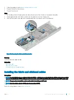
Pressing the release clip on the SATA_A connector, disconnect the connector from the system board.
2
Pressing the release clip on the SATA_B connector, disconnect the connector from the system board.
3
If connected, disconnect the SATA cable from the x16 M.2 riser.
4
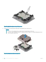
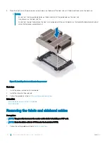
Using the Phillips #1 screwdriver, loosen the captive screws on the linking board and lift the board up along with the cables.
Figure 25. Removing the linking board and SATA cable
Next step
Install the linking board and SATA cable.
Related link
Removing a sled
Removing the air shroud
Removing the support bracket
Installing the linking board and SATA cable
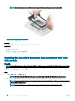
Installing the linking board and SATA cable
Prerequisite
NOTE:
Observe the routing of the cable as you remove it from the sled. Route the cable properly when you replace it to prevent
the cable from being pinched or crimped.
1
Follow the safety guidelines listed in
Steps
1
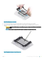
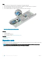
Insert and press the SATA_A connector into the connector on the system board.
2
Insert and press the SATA_B connector into the connector on the system board.
3
If disconnected, reconnect the SATA cable to the x16 M.2 riser.
4
Using the Phillips #1 screwdriver, tighten the captive screws on the linking board to secure the board to the sled.
Installing and removing system components
77
Summary of Contents for EMC PowerEdge C6420
Page 1: ...Dell EMC PowerEdge C6420 Regulatory Model E43S Series Regulatory Type E43S001 ...
Page 8: ...Figure 1 Supported configurations for PowerEdge C6420 8 PowerEdge C6420 overview ...
Page 64: ...Figure 12 Removing a sled 64 Installing and removing system components ...
Page 66: ...Figure 14 Installing a sled 66 Installing and removing system components ...


