5
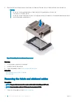
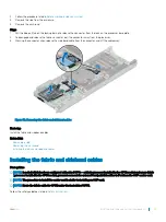
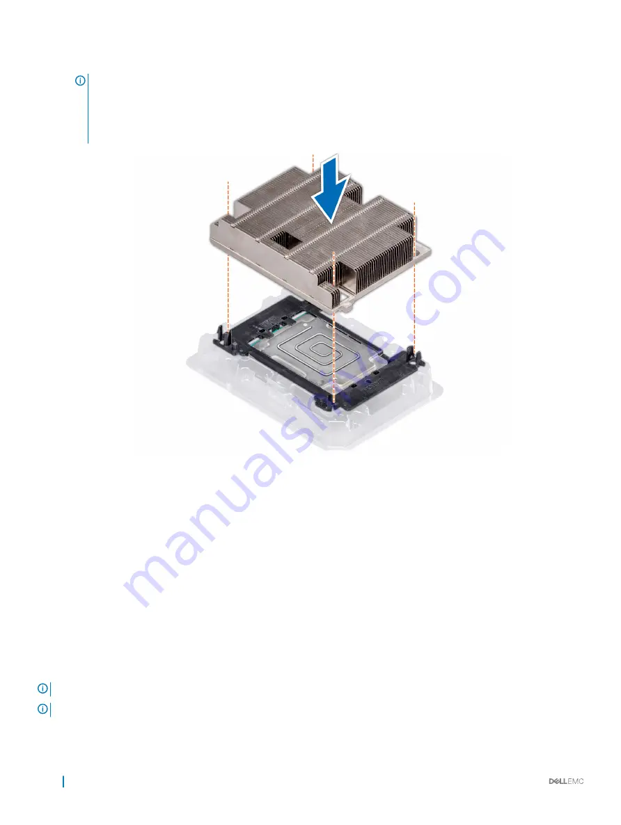
Place the heat sink on the processor and push down on the base of the heat sink until the bracket locks onto the heat sink.
NOTE:
•
Ensure that the two guide pin holes on the bracket match the guide holes on the heat sink.
•
Do not press on the heat sink fins.
•
Ensure that the pin 1 indicator on the heat sink is aligned with the pin 1 indicator on the bracket before placing the heat
sink onto the processor and bracket.
Figure 38. Installing the heat sink onto the processor
Next steps
1
Install the processor and heat sink module.
2
Install the sled into the enclosure.
3
Follow the procedure listed in
After working inside your system
.
Related link
Installing a processor and heat sink module
Installing a sled
Removing the fabric and sideband cables
Prerequisites
NOTE:
The procedure to remove the carrier card is similar to installing an OCP card.
NOTE:
Route the fabric cable for CPU 2 under the heat sink of CPU1.
1
Follow the safety guidelines listed in
90
Installing and removing system components
Summary of Contents for EMC PowerEdge C6420
Page 1: ...Dell EMC PowerEdge C6420 Regulatory Model E43S Series Regulatory Type E43S001 ...
Page 8: ...Figure 1 Supported configurations for PowerEdge C6420 8 PowerEdge C6420 overview ...
Page 64: ...Figure 12 Removing a sled 64 Installing and removing system components ...
Page 66: ...Figure 14 Installing a sled 66 Installing and removing system components ...


