EMC3550
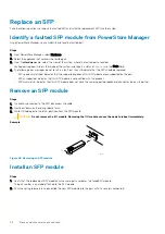
Figure 49. Installing an SFP module
3. Push the spring release down to lock the SFP module into place.
4. Reconnect the cable to the replacement SFP module.
Example
Verify the operation of a replacement part
Steps
1. From PowerStore Manager, select Hardware.
2. Select the appliance where you replaced the faulted part.
3. From the
Hardware
card, select the view of the system where the part was replaced.
The status of the replacement part should read
Healthy
. If the status is still
Faulted
, wait a few minutes and refresh PowerStore
Manager. If the status does not change, ensure that the part is correctly seated, or contact your service provider.
Replace an I/O module
Take the following actions to remove the faulted I/O module and install the replacement I/O module into the system.
Identify a faulted part from PowerStore Manager
Before you replace a part, ensure that you have identified its location within the system. Using PowerStore Manager, you can identify and
locate a faulted part.
Steps
1. From PowerStore Manager, select Hardware.
2. Select the appliance that contains the faulted part.
3. From the
Hardware
card, select the view of the system where the faulted part is located.
Faulted parts appear in red in the image of the system, and report a status of
Faulted
in the State field.
Base enclosure I/O module LEDs
Use the fault LEDs to identify the faulted part.
NOTE:
The ports look different depending on whether they are for copper or optical connections. The image below
shows ports for copper cables.
Base enclosure service procedures
47


