background image

Installing the serial COM port

Prerequisites

1. Follow the safety guidelines listed in the 

Safety instructions

.

2. Follow the procedure listed in 

Before working inside your system

.

3.

Remove the expansion card riser

.

4. Disconnect the serial COM port cable from the connector on the rear I/O board.

Steps

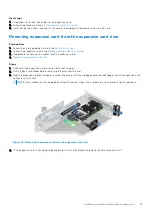
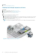
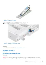
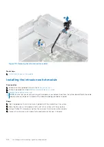
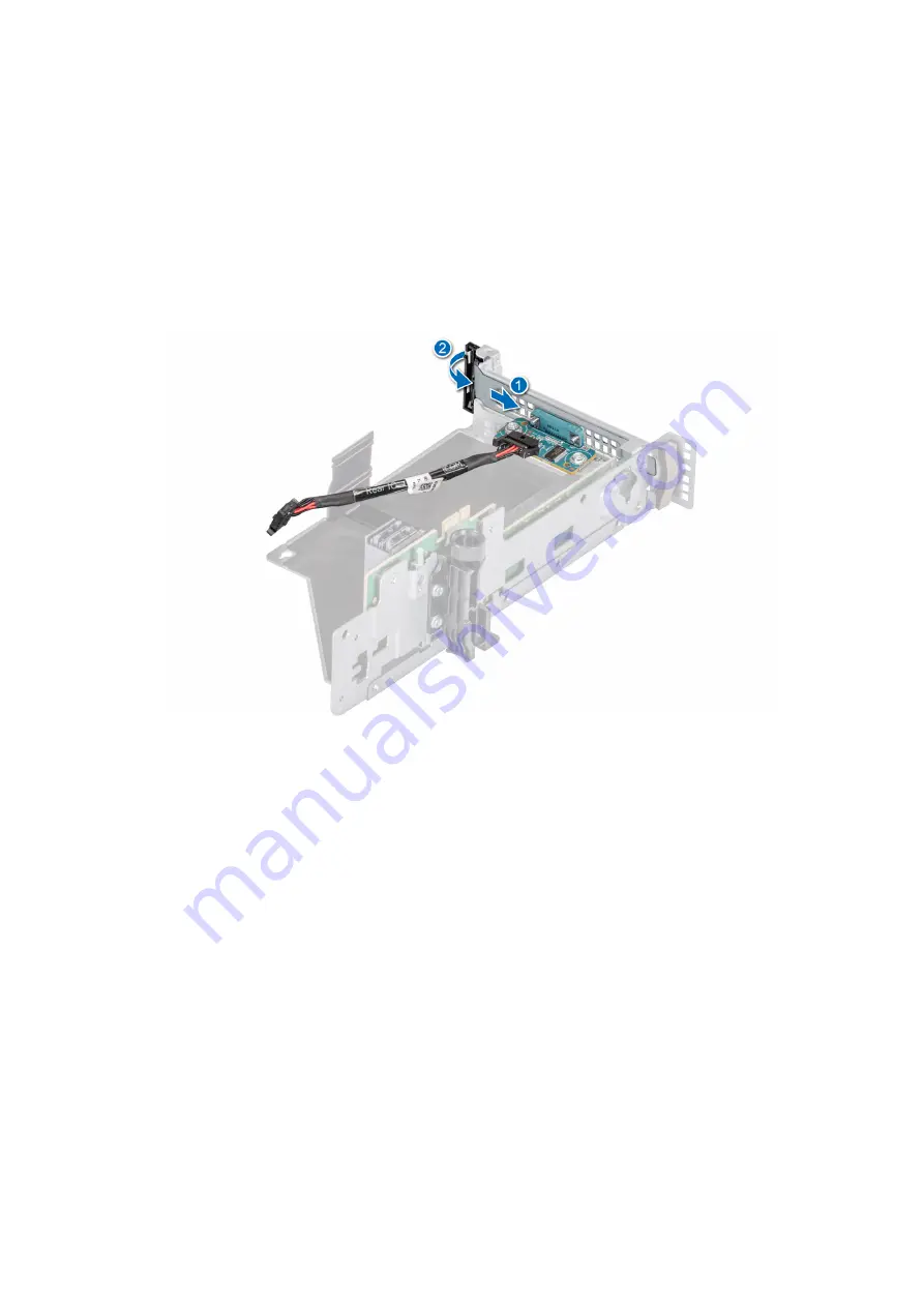
1. Open the latch on the expansion card riser and remove the filler bracket from the expansion card riser (Riser 3).

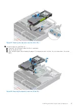
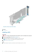
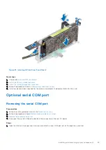
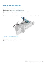
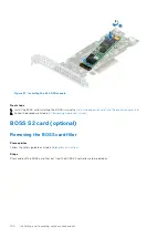
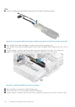
Figure 94. Installing the Serial COM port

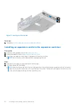
2. Slide the serial COM port into the expansion card riser.
3. Connect the serial COM port cable to the serial port.

Installing and removing system components

97

Summary of Contents for EMC XC Core XC7525

Page 1: ...Dell EMC XC Core XC7525 Installation and Service Manual December 2021 ...

Page 2: ...tial damage to hardware or loss of data and tells you how to avoid the problem WARNING A WARNING indicates a potential for property damage personal injury or death 2021 2021 Dell Inc or its subsidiaries All rights reserved Dell EMC and other trademarks are trademarks of Dell Inc or its subsidiaries Other trademarks may be trademarks of their respective owners ...

Page 3: ... 22 Options to download firmware 22 Options to download and install OS drivers 23 Downloading drivers and firmware 23 Chapter 4 Installing and removing system components 24 Safety instructions 24 Before working inside your system 25 After working inside your system 25 Recommended tools 25 Cable routing 26 RIO card 27 Removing the Rear Input Output RIO card 27 Installing the RIO card 27 Optional fr...

Page 4: ...4 Drive backplane 55 Drive backplane 55 Removing the drive backplane 57 Installing the drive backplane 58 Front PERC module 59 Removing the front mounting front PERC module 59 Installing the front mounting front PERC module 60 Removing the rear mounting front PERC module 61 Installing the rear mounting front PERC module 62 System memory 63 System memory guidelines 63 General memory module installa...

Page 5: ...e OCP card 109 Installing the OCP card 111 Power supply unit 112 Hot spare feature 112 Removing a power supply unit blank 113 Installing a power supply unit blank 113 Removing a power supply unit 113 Installing a power supply unit 114 Trusted Platform Module 115 Upgrading the Trusted Platform Module 115 Initializing TPM for users 116 Initializing the TPM 2 0 for users 116 System board 117 Removing...

Page 6: ...odes 136 Power supply unit indicator codes 136 Drive indicator codes 138 Using system diagnostics 139 Dell Embedded System Diagnostics 139 Chapter 8 Getting help 141 Recycling or End of Life service information 141 Contacting Dell 141 Accessing system information by using QRL 141 Quick Resource Locator for XC Core XC7525 system 142 Receiving automated support with SupportAssist 142 Chapter 9 Docum...

Page 7: ...ument provides an overview about the system information about installing and replacing components technical specifications diagnostic tools and guidelines to be followed while installing certain components 1 About this document 7 ...

Page 8: ...llers Dell PowerEdge Express Flash NVMe PCIe SSD Documentation Manuals and Documents NOTE All instances of SAS SATA drives PCIe SSDs and NVMe are seen as drives in this document unless specified otherwise WARNING Consumer Grade GPU should not be installed or used in the Enterprise Server products For more information about supported drives see the www dell com poweredgemanuals section Topics Front...

Page 9: ...ware or firmware inventory and various system level diagnostic and error information that can be used in troubleshooting the system For more information see the For more information see the Integrated Dell Remote Access Controller User s Guide available at https www dell com idracmanuals 2 Drive N A Enables you to install drives that are supported on your system For more information about drives s...

Page 10: ...system using mobile devices This feature aggregates hardware firmware inventory and various system level diagnostic error information that can be used in troubleshooting the system You can access system inventory Dell Lifecycle Controller logs or system logs system health status and also configure iDRAC BIOS and networking parameters You can also launch the virtual Keyboard Video and Mouse KVM vie...

Page 11: ...ing Blue Blinking Amber Right control panel view Figure 5 Right control panel view Table 4 Right control panel Item Indicator or button Icon Description 1 VGA port Enables you to connect a display device to the system For more information see the www dell com poweredgemanuals section 2 iDRAC Direct port Micro AB USB The iDRAC Direct port Micro AB USB enables you to access the iDRAC Direct Micro AB...

Page 12: ...com poweredgemanuals section 2 BOSS S2 Card optional N A This slot supports the BOSS S2 module 3 Rear Handle N A To lift the system 4 PCIe expansion card riser 2 slot 3 and slot 6 N A The expansion card riser enables you to connect PCI Express expansion cards For more information on the expansion cards that are supported on your system see www dell com poweredgemanuals section 5 PCIe expansion car...

Page 13: ... iDRAC press and hold the button for more than 16 seconds NOTE To reset iDRAC using system ID ensure that the system ID button is enabled in the iDRAC setup If the system stops responding during POST press and hold the system ID button for more than 5 seconds to enter the BIOS progress mode 13 OCP NIC port optional N A This port supports OCP 3 0 The NIC ports are integrated on the OCP card which i...

Page 14: ...6 Heat sink for processor 1 7 Memory DIMM socket for processor 1 E F G H 8 Cooling fan assembly 9 Service tag 10 Drive backplane 11 Cooling fan cage assembly 12 Memory DIMM socket for processor 2 A B C D 13 Heat sink for processor 2 14 System board 15 Power supply unit PSU 2 16 Riser 3 blank 17 Riser 4 blank 14 System overview ...

Page 15: ...the system The information tag is located on the front of the system that includes system information such as Service Tag Express Service Code Manufacture date NIC MAC address QRL label and so on If you have opted for the secure default access to iDRAC the Information tag also contains the iDRAC secure default password If you have opted for iDRAC Quick Sync 2 the Information tag also contains the ...

Page 16: ...rise Service Tag MEST label is located on the rear of the system that includes Service Tag ST Express Service Code Exp Svc Code and Manufacture Date Mfg Date The Exp Svc Code is used by Dell EMC to route support calls to the appropriate personnel Alternatively the Service Tag information is located on a label on left wall of the chassis System information label The system information label is loca...

Page 17: ...Figure 10 Service information System overview 17 ...

Page 18: ...Figure 11 Memory information and system board connectors Figure 12 LED behavior configuration and layout express service tag for 2 5 inch HDD system 18 System overview ...

Page 19: ...k Compatibility Matrix available at https i dell com sites csdocuments Business_solutions_engineering Docs_Documents en rail rack matrix pdf The document provides the information that is listed below Specific details about rail types and their functionalities Rail adjustability ranges for various rack mounting flange types Rail depth with and without cable management accessories Rack types that ar...

Page 20: ...tegrated Dell Remote Access Controller iDRAC is designed to make you more productive as a system administrator and improve the overall availability of Dell EMC servers iDRAC alerts you to system issues helps you to perform remote management and reduces the need for physical access to the system Options to set up iDRAC IP address To enable communication between your system and iDRAC you must first ...

Page 21: ...stem that has the shared LOM mode enabled Options to set up iDRAC IP address To enable communication between your system and iDRAC you must first configure the network settings based on your network infrastructure The network settings option is set to DHCP by default NOTE For static IP configuration you must request for the setting at the time of purchase You can set up the iDRAC IP address using ...

Page 22: ...available on back side of the Information Tag If you have not opted for secure default access to iDRAC enter the default user name and password root and calvin You can also log in by using your Single Sign On or Smart Card NOTE Ensure that you change the default username and password after setting up the iDRAC IP address For more information about logging in to the iDRAC and iDRAC licenses see the...

Page 23: ... and for latest documentation version see https www dell com support article sln308699 Downloading drivers and firmware It is recommended that you download and install the latest BIOS drivers and systems management firmware on the system Prerequisites Ensure that you clear the web browser cache before downloading the drivers and firmware Steps 1 Go to https www dell com support drivers 2 Enter the...

Page 24: ...oard Safety instructions NOTE To avoid injury do not lift the system on your own Get others to assist you CAUTION Many repairs may only be done by a certified service technician You should only perform troubleshooting and simple repairs as authorized in your product documentation or as directed by the online or telephone service and support team Damage due to servicing that is not authorized by De...

Page 25: ...Safety instructions Steps 1 Power off the system and all attached peripherals 2 Disconnect the system from the electrical outlet and disconnect the peripherals 3 If applicable remove the system from the rack For more information see the Rail Installation Guide relevant to your rail solutions at https www dell com poweredgemanuals 4 Remove the system cover After working inside your system Prerequis...

Page 26: ...Cable routing Figure 14 12x 3 5 inch Figure 15 24 x 2 5 inch SAS SATA hard drives 26 Installing and removing system components ...

Page 27: ... edges pull the RIO card to disconnect from the connector on the system board Figure 16 Removing the RIO card Next steps 1 Install the RIO card Installing the RIO card Prerequisites 1 Follow the safety guidelines listed in the Safety instructions 2 Follow the procedure listed in Before working inside your system 3 Remove the system board 4 If required Remove the LOM card NOTE Upgrading the system ...

Page 28: ...ard 2 Follow the procedure listed in After working inside your system Optional front bezel Removing the front bezel The procedure to remove the front bezel with and without the LCD panel is the same Prerequisites 1 Follow the safety guidelines listed in the Safety instructions 2 Keep the bezel key handy NOTE The bezel key is part of the LCD bezel package Steps 1 Unlock the bezel 2 Press the releas...

Page 29: ...is the same Prerequisites 1 Follow the safety guidelines listed in the Safety instructions 2 Locate and remove the bezel key NOTE The bezel key is part of the LCD bezel package Steps 1 Align and insert the tabs on the bezel into the slots on the system 2 Press the bezel until the release button clicks in place 3 Lock the bezel Installing and removing system components 29 ...

Page 30: ...ff the system and any attached peripherals 3 Disconnect the system from the electrical outlet and peripherals Steps 1 Using a 1 4 inch flat head or a Phillips 2 screwdriver rotate the lock counterclockwise to the unlock position 2 Lift the release latch until the system cover slides back 3 Lift the cover from the system 30 Installing and removing system components ...

Page 31: ...nside your system 3 Ensure that all internal cables are connected and routed properly and no tools or extra parts are left inside the system Steps 1 Align the tabs on the system cover with the guide slots on the system and slide the system cover 2 Close the system cover release latch 3 Using a 1 4 inch flat head or Phillips 2 screwdriver rotate the lock clockwise to the lock position Installing an...

Page 32: ...ive backplane cover Prerequisites 1 Follow the safety guidelines listed in the Safety instructions 2 Follow the procedure listed in Before working inside your system Steps 1 Slide the backplane cover in the direction of the arrows marked on the drive backplane cover 2 Lift the backplane cover from the system 32 Installing and removing system components ...

Page 33: ...plane cover Prerequisites 1 Follow the safety guidelines listed in the Safety instructions Steps 1 Align the drive backplane cover with the guide slots on the system 2 Slide the drive backplane cover to the front of the system until the drive backplane cover fits into place Installing and removing system components 33 ...

Page 34: ...ve the side wall bracket Steps 1 Using the Phillips 1 screwdriver remove the screws that secure the right control panel and the right control panels cable cover to the system and remove the cable cover away the system 2 Disconnect the right control panel cable and the VGA cable from the connectors on the system board 3 Holding the cable slide the right control panel out of the system NOTE Observe ...

Page 35: ...t on the system 2 Connect the right control panel cable and VGA cable to the connectors on the system board 3 Route the right control panel cable through the side wall of the system Align and slide the right control panel cable cover in the slot on the system NOTE Route the cable properly to prevent the cable from being pinched or crimped 4 Using the Phillips 1 screwdriver tighten the screws that ...

Page 36: ... 4 If removed Install the air shroud 5 Follow the procedure listed in After working inside your system Removing the left control panel Prerequisites 1 Follow the safety guidelines listed in the Safety instructions 2 Follow the procedure listed in the Before working inside your system 3 Remove the drive backplane cover 4 If installed Remove the air shroud 5 Remove the cooling fan assembly 6 Remove ...

Page 37: ...f sequence Figure 26 Removing the left control panel Next steps 1 Install the left control panel Installing the left control panel Prerequisites 1 Follow the safety guidelines listed in the Safety instructions 2 Follow the procedure listed in Before working inside your system Steps 1 Align and slide the left control panel in the slot on the system 2 Connect the left control panel cable to the conn...

Page 38: ...t depict the exact steps The numbers are for representation of sequence Figure 27 Installing the left control panel Next steps 1 Install the side wall bracket 2 Install the cooling fan assembly 3 Install the drive backplane cover 4 If removed Install the air shroud 5 Follow the procedure listed in After working inside your system 38 Installing and removing system components ...

Page 39: ...ure listed in Before working inside your system Steps Hold the edges of the air shroud and lift the air shroud out of the system Figure 28 Removing the air shroud Next steps 1 Install the air shroud Installing the air shroud Prerequisites 1 Follow the safety guidelines listed in the Safety instructions 2 Follow the procedure listed in Before working inside your system Steps 1 Align the slot on the...

Page 40: ...tes CAUTION Never operate your system with the air shroud removed The system may get overheated quickly resulting in shutdown of the system and loss of data 1 Follow the safety guidelines listed in the Safety instructions 2 Follow the procedure listed in Before working inside your system Steps Hold the edges of the GPU air shroud and lift the air shroud out of the system 40 Installing and removing...

Page 41: ... Follow the safety guidelines listed in the Safety instructions 2 Follow the procedure listed in Before working inside your system Steps 1 Align the slot on the GPU air shroud with the standoff on the system 2 Lower the GPU air shroud into the system until it is firmly seated Installing and removing system components 41 ...

Page 42: ... with the air shroud removed The system may get overheated quickly resulting in shutdown of the system and loss of data 1 Follow the safety guidelines listed in the Safety instructions 2 Follow the procedure listed in Before working inside your system Steps Press the blue tabs on either sides of the top cover and lift the top cover out of the GPU air shroud 42 Installing and removing system compon...

Page 43: ...Prerequisites 1 Follow the safety guidelines listed in the Safety instructions 2 Follow the procedure listed in Before working inside your system Steps 1 Align the tabs on the top cover with the slots on the GPU air shroud 2 Lower the top cover into the GPU air shroud until it is firmly seated Installing and removing system components 43 ...

Page 44: ... 1 Follow the safety guidelines listed in the Safety instructions 2 Follow the procedure listed in Before working inside your system 3 If installed Remove the air shroud Steps 1 Lift the blue release levers to unlock the cooling fan cage assembly from the system 2 Hold the release levers and lift the cooling fan cage assembly away from the system 44 Installing and removing system components ...

Page 45: ...lling the cooling fan cage assembly Incorrectly installed cables may get damaged 2 Follow the procedure listed in Before working inside your system 3 If installed Remove the air shroud Steps 1 Align the guide rails on the cooling fan cage assembly with the standoffs on the system 2 Lower the cooling fan cage assembly into the system until the cooling fan cage connectors engage with the connectors ...

Page 46: ...s 2 Follow the procedure listed in Before working inside your system 3 If installed Remove the air shroud Steps Press the orange release tab and lift the cooling fan to disconnect the fan from the connector on the system board NOTE The procedure to remove standard high performance silver grade or high performance gold grade fan is same WARNING Ensure not to tilt or rotate the cooling fan while rem...

Page 47: ... the Safety instructions 2 Follow the procedure listed in Before working inside your system Steps Align and slide the cooling fan into the cooling fan assembly until the fan clicks into place NOTE The procedure to install standard high performance silver grade or high performance gold grade fan is same Installing and removing system components 47 ...

Page 48: ...emove the front bezel 4 Remove the drive backplane cover 5 If installed Remove the air shroud 6 Remove the cooling fan assembly NOTE Ensure that you note the routing of the cables as you remove them from the system board Route the cable properly when you replace it to prevent the cable from being pinched or crimped Steps 1 Press the tab to release the side wall bracket cover NOTE Unroute the cable...

Page 49: ...Remove the air shroud NOTE Ensure that you note the routing of the cables as you remove them from the system board Route the cable properly when you replace it to prevent the cable from being pinched or crimped Steps 1 Align the side wall bracket with the tabs on the chassis 2 Press the side wall bracket with your thumbs until the bracket firmly clicks into place NOTE Route the cables through the ...

Page 50: ...dure listed in the After working inside your system Drives Removing a drive blank Prerequisites 1 Follow the safety guidelines listed in the Safety instructions 2 If installed Remove the front bezel CAUTION To maintain proper system cooling drive blanks must be installed in all empty drive slots Steps Press the release button and slide the drive blank out of the drive slot 50 Installing and removi...

Page 51: ...ank Next steps 1 If removed Install the front bezel Removing the drive carrier Prerequisites 1 Follow the safety guidelines listed in the Safety instructions 2 If installed Remove the front bezel 3 Using the management software prepare the drive for removal If the drive is online the green activity or fault indicator blinks while the drive is powering off When the drive indicators are off the driv...

Page 52: ...g a drive while the system is running see the documentation for the storage controller card to ensure that the host adapter is configured correctly to support drive removal and insertion CAUTION Combining SAS and SATA drives in the same RAID volume is not supported CAUTION When installing a drive ensure that the adjacent drives are fully installed Inserting a drive carrier and attempting to lock i...

Page 53: ... the drive carrier release handle to lock the drive in place Figure 43 Installing a drive carrier Next steps If removed Install the front bezel Removing the drive from the drive carrier Prerequisites 1 Follow the safety guidelines listed in the Safety instructions 2 If installed Remove the front bezel Steps 1 Using a Phillips 1 screwdriver remove the screws from the slide rails on the drive carrie...

Page 54: ...e drive into the drive carrier with the drive connector facing towards the rear of the carrier 2 Align the screw holes on the drive with the screws holes on the drive carrier 3 Using a Phillips 1 screwdriver secure the drive to the drive carrier with the screws NOTE When installing a drive into the drive carrier ensure that the screws are torqued to 4 lbf in NOTE If the hard drive or SSD carrier h...

Page 55: ...ne Depending on your system configuration the drive backplanes supported are listed here Table 9 Supported backplane options System Supported hard drives options XC Core XC7525 3 5 inch x12 SAS or SATA backplane 2 5 inch x8 SAS SATA or NVMe backplane 2 5 inch x16 SAS or SATA backplane 2 5 inch x24 NVMe backplane Installing and removing system components 55 ...

Page 56: ...board 7 DST_PB2 PCIe NVMe connector Figure 47 12x 3 5 inch drive backplane 1 BP_DST_SB1 2 BP_PWR_1 backplane power and signal cable to system board 3 BP_DST_SA1 Figure 48 16 x 2 5 inch drive backplane 1 BP_DST_SB1 backplane to front PERC 2 BP_PWR_1 backplane power and signal cable to system board 3 BP_PWR_CTRL front PERC power and control signal 4 BP_DST_SA1 backplane to front PERC 56 Installing a...

Page 57: ... all backplane configurations 1 Follow the safety guidelines listed in the Safety instructions 2 Follow the procedure listed in the Before working inside your system 3 Remove the drive backplane cover 4 If installed Remove the air shroud 5 Install all drives 6 Remove the cooling fan cage assembly 7 Disconnect the drive backplane cables from the connector on the system board 8 Disconnect the drive ...

Page 58: ...bly NOTE To avoid damaging the backplane ensure to move the control panel cables from the cable routing clips before removing the backplane NOTE Route the cable properly when you replace it to prevent the cable from being pinched or crimped Steps 1 Use the guides on the system as guides to align the slots on the backplane 2 Insert the backplane into the guides and lower the backplane until the blu...

Page 59: ...side your system Front PERC module Removing the front mounting front PERC module Prerequisites 1 Follow the safety guidelines listed in the Safety instructions 2 Follow the procedure listed in Before working inside your system 3 Remove the drive backplane cover 4 If installed Remove the air shroud 5 Disconnect all the cables observe the cable routing Steps 1 Using a Phillips 2 screwdriver loosen t...

Page 60: ...nstalled Remove the air shroud 5 Route the cable properly to prevent the cable from being pinched or crimped Steps 1 Align the front PERC module at an angle until the tray touches the slot in the system 2 Slide and press the front PERC module connector with the connector on the drive backplane until firmly seated 3 Using a Phillips 2 screwdriver tighten the captive screws on the front PERC module ...

Page 61: ...cedure listed in Before working inside your system 3 Remove the drive backplane cover 4 If installed Remove the air shroud 5 Remove the drive backplane 6 Disconnect all the cables observe the cable routing Steps 1 Using a Phillips 2 screwdriver loosen the captive screws on the front PERC module NOTE The mounting bracket for the 24 x 2 5 inch backplane is on the right of the backplane The removal o...

Page 62: ... cable from being pinched or crimped Steps 1 Align the connectors and guide slots on the front PERC module with the connectors and guide pins on the drive backplane NOTE The mounting bracket for the 24 x 2 5 inch backplane is on the right of the backplane The installation of the PERC module is on the right side of the backplane 2 Slide the front PERC module until the module is connected to the dri...

Page 63: ...e your system System memory System memory guidelines The XC Core XC7525 system supports DDR4 registered DIMMs RDIMMs and Load Reduced DIMM LRDIMMs System memory holds the instructions that are started by the processor Your system memory is organized into eight channels per processor two memory sockets per channel 16 memory sockets per processor and 32 memory sockets per system Installing and remov...

Page 64: ...ts B5 and B11 Slots B2 and B10 Slots B1 and B9 Slots B8 and B16 Slots B7 and B15 Slots B4 and B14 Slots B3 and B13 Table 11 Supported memory matrix DIMM type Rank Capacity DIMM rated voltage and speed Operating Speed on AMD EPYC processor 1 DIMM per channel DPC 2 DIMMs per channel DPC RDIMM 2 R 16 GB 32 GB 64 GB DDR4 1 2 V 3200 MT s 3200 MT s 2933 MT s LRDIMM 4 R 128 GB DDR4 1 2 V 3200 MT s 3200 M...

Page 65: ...ce Table 12 Memory population rules Processor Configuration Memory population Memory population information Dual processor Start with processor1 Processor 1 and processor 2 population should match Optimizer Independent channel population order A 1 B 1 A 2 B 2 A 3 B 3 A 4 B 4 A 5 B 5 A 6 B 6 A 7 B 7 A 8 B 8 Odd amount of DIMMs per processor is allowed DIMMs must be populated identically per process...

Page 66: ...the preferred interleaving BIOS shows a warning message UEFI0391 NOTE System is functional when UEFI0391 message is displayed However the system may not be configured for optimal performance NPS system optimization Optimal system configuration is dependent on the processor model memory configuration and NPS settings The following processor modules are supported 75F3 7763 74F3 73F3 7713 7543 7513 7...

Page 67: ... memory modules populated Single processor system creates a single NUMA node for the system NOTE An exception is allowed when system has 4 channels populated C D G H with equal memory allowing the system to enter NPS1 mode even though all the 8 channels are not populated NPS0 Sixteen channel interleaving dual processor This interleaves all 16 channels in a dual processor system All channels in a s...

Page 68: ...lled in the socket remove it 3 Align the edge connector of the memory module with the alignment key of the memory module socket and insert the memory module in the socket NOTE Ensure the memory socket ejectors are fully open NOTE The memory module socket has an alignment key that enables you to install the memory module in the socket in only one orientation CAUTION Do not apply pressure at the cen...

Page 69: ...cs Processor and heat sink Removing a heat sink Prerequisites 1 Follow the safety guidelines listed in the Safety instructions 2 Follow the procedure listed in Before working inside your system 3 If installed Remove the air shroud WARNING The heat sink and processor are too hot to touch for some time after the system has been powered off Allow the heat sink and processor to cool down before handli...

Page 70: ...moving it 1 Follow the safety guidelines listed in the Safety instructions 2 Follow the procedure listed in Before working inside your system 3 Remove the heat sink CAUTION You may find the CMOS battery loss or CMOS checksum error is displayed during the first instance of powering on the system after the processor or system board replacement which is expected To fix go to set up option to configur...

Page 71: ...ce plate 2 Release the processor socket rail frame by lifting the blue latches Figure 61 Lifting the rail frame 3 Holding the blue tab on the processor tray slide the tray out of the rail frame Installing and removing system components 71 ...

Page 72: ...llow the safety guidelines listed in the Safety instructions 2 Follow the procedure listed in Before working inside your system 3 Remove the heat sink Steps 1 Holding the blue tab on the processor tray slide the tray into the processor socket rail frame until firmly seated 72 Installing and removing system components ...

Page 73: ...e by tightening the screws in the sequence 1 2 and 3 When all three screws are fully threaded the socket is then actuated The three screws are tightened to a torque value of 12 0 1 2 lbf in NOTE The screw numbers are marked on the force plate NOTE Press the force plate while tightening the screws to avoid tilting of the processor cover out of the processor socket Installing and removing system com...

Page 74: ...re listed in the Before working inside your system 3 If installed Remove the air shroud 4 If installed remove the processor dust cover NOTE The procedure to install standard and L type heat sink is similar Steps 1 If you are using an existing heat sink remove the thermal grease on the heat sink by using a clean lint free cloth NOTE For a new heat sink the thermal paste is preapplied to the heat si...

Page 75: ...A1 extrusion on the L type heat sink should face towards the system side 4 Using a Torx T20 screwdriver tighten the captive screws in the order that is mentioned below NOTE The captive screw numbers are marked on the heat sink and are tightened to a torque value of 12 0 1 2 lbf in a Partially tighten the captive screws 1 and 2 approximately 3 turns b Partially tighten the captive screws 3 and 4 ap...

Page 76: ...sage see Troubleshooting expansion cards section in the Dell EMC PowerEdge Servers Troubleshooting Guide at https www dell com poweredgemanuals Expansion card installation guidelines The following table describes the supported expansion cards Table 14 Expansion card riser configurations Expansion card riser PCIe slots Processor connection Height Length Slot width Riser 1 Slot 1 Processor 1 Full He...

Page 77: ...l Length Card type Slot priority Maximum number of cards Dell Serial 4 1 NVIDIA GPU Low Profile 3 6 2 NVIDIA GPU Full Height 2 7 2 NVIDIA GPU Full Height 2 5 7 3 FOXCONN front PERC Internal slot 1 Inventec front PERC Internal slot 1 FOXCONN PERC Adapter Low Profile 3 1 Inventec PERC Adapter Low Profile 3 1 Mellanox NIC 100 Gb Low Profile 3 6 2 Intel NIC 25 Gb Low Profile 3 6 2 Mellanox NIC 25 Gb L...

Page 78: ...n the riser a Press the blue release tab and holding the edges lift the expansion card riser from the riser connector on the system board NOTE The numbers on the image do not depict the exact steps The numbers are for representation of sequence Figure 68 Removing the expansion card riser Riser 1 2 For Riser 2 press the blue button on the riser and holding the touch points lift the expansion card r...

Page 79: ...ansion card riser from the riser connector on the system board Figure 70 Removing the expansion card riser Riser 3 4 For Riser 4 loosen the captive screw on the riser and then press the blue release tab on the riser and holding the touch point lift the expansion card riser from the riser connector on the system board Installing and removing system components 79 ...

Page 80: ...to the expansion card risers Steps 1 Holding the edges or the touch points align the holes on the expansion card riser with the guides on the system board 2 Lower the expansion card riser into place and press the touch points until the expansion card riser connector is fully seated on the system board connector 3 Tighten the captive screws on the risers and system if any NOTE The numbers on the im...

Page 81: ...Figure 72 Installing the expansion card riser Riser 1 Figure 73 Installing the expansion card riser Riser 2 Installing and removing system components 81 ...

Page 82: ...Figure 74 Installing the expansion card riser Riser 3 Figure 75 Installing the expansion card riser Riser 4 82 Installing and removing system components ...

Page 83: ...les from the expansion card 4 Remove the expansion card riser Steps 1 Pull and lift the expansion card retention latch lock to open 2 Pull the black card holder before removing the card from the riser 3 Hold the expansion card by the edges and pull the card until the card edge connector disengages from the expansion card connector on the riser NOTE The numbers on the image do not depict the exact ...

Page 84: ...pack it and prepare the card for installation NOTE For instructions see the documentation accompanying the card Steps 1 Pull and lift up the expansion card retention latch lock to open 2 If installed remove the filler bracket NOTE Store the filler bracket for future use Filler brackets must be installed in empty expansion card slots to maintain Federal Communications Commission FCC certification o...

Page 85: ...mbers on the image do not depict the exact steps The numbers are for representation of sequence Figure 79 Installing an expansion card into the expansion card riser Next steps 1 If applicable connect the cables to the expansion card 2 Follow the procedure listed in After working inside your system 3 Install any device drivers required for the card as described in the documentation for the card Rem...

Page 86: ...ystem board c Disconnect the GPU power cable from the system board NOTE The numbers on the image do not depict the exact steps The numbers are for representation of sequence Figure 80 Removing the expansion card riser Riser 1A 2 To remove expansion card Riser 3A a Press the blue button on the riser and holding the touch points lift the expansion card riser from the riser connector on the system bo...

Page 87: ...nnect the GPU power cable from the system board b Loosen the captive screw c Press the blue release tab and holding the edges lift the expansion card riser from the riser connector on the system board Figure 82 Removing the expansion card riser Riser 4A Installing and removing system components 87 ...

Page 88: ...nnect the GPU cable to the system board b Holding the edges or the touch points align the holes on the expansion card riser with the guides on the system board c Lower the expansion card riser into place and press the touch points until the expansion card riser connector is fully seated on the system board connector d Tighten the captive screws on the risers and system if any NOTE The numbers on t...

Page 89: ...d riser with the guides on the system board b Lower the expansion card riser into place and press the touch points until the expansion card riser connector is fully seated on the system board connector c Tighten the captive screw on the riser d Connect the GPU cable to the system board Figure 85 Installing the expansion card riser Riser 4A Installing and removing system components 89 ...

Page 90: ... from the expansion card 4 Remove the GPU air shroud top cover 5 Remove the full length expansion card riser Steps 1 To remove the GPU from Riser 1 a Disconnect the GPU power cable from the GPU card b Press the button and pull the black card holder before removing the GPU card from the riser c Open the expansion card holder latch on the riser d Hold the GPU card by the edges and pull the card unti...

Page 91: ...ctor on the riser Figure 87 Removing GPU 3 and 4 3 If you are removing the GPU permanently install a filler bracket NOTE You must install a filler bracket over an empty expansion card slot to maintain Federal Communications Commission FCC certification of the system The brackets also keep dust and dirt out of the system and aid in proper cooling and airflow inside the system The filler bracket is ...

Page 92: ...s listed in the Safety instructions 2 Follow the procedure listed in Before working inside your system 3 If installing a new expansion card unpack it and prepare the card for installation NOTE For instructions see the documentation accompanying the card 4 Remove the GPU air shroud top cover Steps 1 Open the expansion card latch and remove the metal filler bracket away from the riser 92 Installing ...

Page 93: ...ith the connector on the riser b Insert the GPU into the riser until it is fully seated c Close the expansion card holder latch d Press the black card holder latch on the GPU and riser to secure the GPU card to the riser e Connect the GPU power cable to the GPU card Installing and removing system components 93 ...

Page 94: ...iser b Insert the GPU into the riser until it is fully seated c Close the expansion card holder latch d Press the black card holder latch on the GPU and riser to secure the GPU card to the riser e Connect the GPU power cable to the GPU card f Slide back the expansion card latch on the riser 94 Installing and removing system components ...

Page 95: ...ribed in the documentation for the card Optional serial COM port Removing the serial COM port Prerequisites 1 Follow the safety guidelines listed in the Safety instructions 2 Follow the procedure listed in Before working inside your system 3 Remove the expansion card riser 4 Disconnect the serial COM port cable from the connector on the rear I O board Steps 1 Open the latch on the expansion card r...

Page 96: ...emoving the Serial COM port 2 Disconnect the serial COM port cable from the serial port Figure 93 Removing the Serial COM port Next steps 1 Install the serial COM port 96 Installing and removing system components ...

Page 97: ...d riser 4 Disconnect the serial COM port cable from the connector on the rear I O board Steps 1 Open the latch on the expansion card riser and remove the filler bracket from the expansion card riser Riser 3 Figure 94 Installing the Serial COM port 2 Slide the serial COM port into the expansion card riser 3 Connect the serial COM port cable to the serial port Installing and removing system componen...

Page 98: ...he Safety instructions 2 Follow the procedure listed in Before working inside your system 3 Remove the BOSS card The BOSS card removal is similar to Removing an expansion card from the expansion card riser Steps 1 Using the Phillips 1 screwdriver remove the screws securing the M 2 SSD module to the BOSS card 2 Pull the M 2 SSD module to disconnect from the BOSS card connector NOTE The numbers on t...

Page 99: ...rking inside your system 3 Remove the BOSS card Removing BOSS card is similar to Removing an expansion card from the expansion card riser Steps 1 Align the M 2 SSD module at an angle with the BOSS card connector 2 Insert the M 2 SSD module until it is firmly seated in the BOSS card connector 3 Using the Phillips 1 screwdriver secure the M 2 SSD module on the BOSS card with the screw Installing and...

Page 100: ...pansion card riser 2 Follow the procedure listed in After working inside your system BOSS S2 card optional Removing the BOSS card filler Prerequisites Follow the safety guidelines listed in the Safety instructions Steps Press and pull the BOSS card filler out from the BOSS S2 controller card module bay 100 Installing and removing system components ...

Page 101: ... Installing the BOSS card filler Prerequisites 1 Follow the safety guidelines listed in the Safety instructions Steps Align the BOSS card filler with the BOSS S2 controller card module bay and push it into the bay until it clicks into place Figure 99 Installing the BOSS card filler Installing and removing system components 101 ...

Page 102: ...illips 1 screwdriver remove the M3 x 0 5 x 4 5 mm screw that secures the M 2 SSD to the BOSS S2 card carrier 4 Slide the M 2 SSD out and up from the BOSS S2 card carrier Figure 101 Removing the M 2 SSD 5 Disconnect the BOSS power cable and the BOSS signal cable from the system board 6 Using the Phillips 1 screwdriver remove the M3 x 0 5 x 4 5 mm screw that secures the BOSS S2 controller card modul...

Page 103: ...and BOSS signal cable from the BOSS S2 controller card module Next steps 1 Remove the BOSS S2 controller card module or Install the BOss card filler Installing the BOSS S2 controller card module Prerequisites 1 Follow the safety guidelines listed in the Safety instructions 2 Follow the procedure listed in the Before working inside your system Installing and removing system components 103 ...

Page 104: ... the chassis until it is secured 4 Using the Phillips 1 screwdriver secure the BOSS S2 controller card module with the M3 x 0 5 x 4 5 mm screw 5 Connect the BOSS power cable and the BOSS signal cable to the connectors on the system board Figure 105 Installing the BOSS S2 controller card module 6 Align the M 2 SSD at an angle with the BOSS S2 card carrier 7 Insert the M 2 SSD until it is firmly sea...

Page 105: ...he BOSS S2 card carrier Next steps 1 Follow the procedure listed in the After working inside your system System battery Replacing the system battery Prerequisites WARNING There is a danger of a new battery exploding if it is incorrectly installed Replace the battery only with the same or equivalent type That is recommended by the manufacturer Discard used batteries Installing and removing system c...

Page 106: ...n cards 4 Remove the expansion card risers Steps 1 To remove the battery a Use a plastic scribe to pry out the system battery CAUTION To avoid damage to the battery connector you must firmly support the connector while installing or removing a battery Figure 108 Removing the system battery 2 To install a new system battery a Hold the battery with the positive side facing up and slide it under the ...

Page 107: ...e still incorrect see Getting help section Intrusion switch module Removing the intrusion switch module Prerequisites 1 Follow the safety guidelines listed in the Safety instructions 2 Follow the procedure listed in Before working inside your system 3 Remove the expansion card riser NOTE Ensure that you note the routing of the cables as you remove them from the system board Route the cable properl...

Page 108: ...e the routing of the cables as you remove them from the system board Route the cable properly when you replace it to prevent the cable from being pinched or crimped Steps 1 Align the guides on the intrusion switch module with the standoffs on the system 2 Slide the intrusion switch module into the slot in the system until firmly seated 3 Using a Phillips 2 screwdriver tighten the screw on the intr...

Page 109: ...ollow the safety guidelines listed in the Safety instructions 2 Follow the procedure listed in Before working inside your system 3 Remove the expansion card riser Steps 1 Open the blue latch to disengage the OCP card 2 Push the OCP card towards the rear end of the system to disconnect from the connector on the system board 3 Slide the OCP card out of the slot on the system Installing and removing ...

Page 110: ...emoving the OCP card 4 If the OCP card is not going to be replaced install a filler bracket Figure 113 Installation of filler bracket Next steps 1 Install the OCP card 110 Installing and removing system components ...

Page 111: ...ve the filler bracket Figure 114 Removal of filler bracket 2 Open the blue latch on the system board 3 Slide the OCP card into the slot in the system 4 Push until the OCP card is connected to the connector on the system board 5 Close the latch to lock the OCP card to the system NOTE The numbers on the image do not depict the exact steps The numbers are for representation of sequence Installing and...

Page 112: ... active PSU supports 100 percent of the system load thus operating at higher efficiency The PSU in the sleep state monitors output voltage of the active PSU If the output voltage of the active PSU drops the PSU in the sleep state returns to an active output state If having both PSUs active is more efficient than having one PSU in the sleep state the active PSU can also activate the sleeping PSU Th...

Page 113: ...icks into place Removing a power supply unit Prerequisites CAUTION The system requires one power supply unit PSU for normal operation On power redundant systems remove and replace only one PSU at a time in a system that is powered on 1 Follow the safety guidelines listed in the Safety instructions 2 Disconnect the power cable from the power outlet and from the PSU you intend to remove 3 Remove the...

Page 114: ...ed in the Safety instructions 2 For systems that support redundant PSU ensure that both the PSUs are of the same type and have the same maximum output power NOTE The maximum output power shown in watts is listed on the PSU label 3 Remove the PSU blank Steps Slide the PSU into the PSU bay until the release latch snaps into place 114 Installing and removing system components ...

Page 115: ...tus The PSU redundancy may not occur until discovery is complete The PSU status indicator turns green to indicate that the PSU is functioning properly Trusted Platform Module Upgrading the Trusted Platform Module Prerequisites NOTE Ensure that your operating system supports the version of the TPM module being installed Ensure that you download and install the latest BIOS firmware on your system En...

Page 116: ...nnector such that the plastic rivet aligns with the slot on the system board 3 Press the plastic rivet until the rivet snaps into place 4 Replace the screw that secures the TPM to the system board Figure 118 Installing the TPM Initializing TPM for users Steps 1 Initialize the TPM For more information see Initializing the TPM for users 2 The TPM Status changes to Enabled Activated Initializing the ...

Page 117: ...listed in Before working inside your system 3 Remove the following components a Air shroud if installed b Cooling fan cage assembly c Heat sink d Processor e Memory modules f Expansion card risers g IDSDM module if installed h Internal USB card if installed i OCP card if installed j Power supply unit PSU k Rear drive cage l Disconnect all cables from the system board CAUTION Take care not to damag...

Page 118: ...ON Do not lift the system board by holding a memory module processor or other components CAUTION Take care not to damage the system identification button while placing the system board into the chassis 2 Holding the system board holder and plunger lower the system board into the system 3 Slide the system board towards the rear of the chassis until the connectors are firmly seated in the slots Figu...

Page 119: ...configuration data after replacing the system board All data is backed up in a backup Flash drive device automatically If BIOS detects a new system board and the Service Tag in the backup Flash drive device is different BIOS prompts the user to restore the backup information About this task Below is a list of options available 1 Restore the Service Tag license and diagnostics information press Y 2...

Page 120: ...stem board Steps 1 Using a Phillips 2 screwdriver remove the screws that secure the LAN on Motherboard LOM card and rear I O board to the system board 2 Holding the edges pull the LOM card or rear I O board to disconnect from the connector on the system board Figure 121 Removing the LOM card and rear I O board Next steps 1 Install the LOM card and rear I O board Installing the LOM card and rear I ...

Page 121: ...oard until firmly seated on the system board connector 3 Using a Phillips 2 screwdriver secure the LOM card or rear I O board to the system board with screws Figure 122 Installing the LOM card and rear I O board Next steps 1 Install the system board 2 Follow the procedure listed in After working inside your system Installing and removing system components 121 ...

Page 122: ...ons GPU See GPU kit Hard drives See Installing the drive carrier Hard drives SSD See Installing the drive into the drive carrier Memory See Installing a mempory module Network cards Standard PCIe adapter LP FH See Installing the LOM card and rear I O board Network cards OCP See Installing the OCP card Topics GPU kit 5 122 Upgrade Kits ...

Page 123: ...I cable Power cables 3 x 6 2 pin power cables 3 x 8 pin power cables Foam Mylar foam 1 Mylar foam 1 FL Full Length HL Half Length You may not need all the components in the kit for GPU installation For information about riser configurations see the expansion card installation guidelines section NOTE XGMI cable might be installed in the system if not available install the XGMI cable from the kit fo...

Page 124: ...uration Riser Riser slots Processor System riser configuration Riser card type GPU slots Riser 1 Slot 1 Processor 1 Configuration 3 R1A FH FL or HL 2 Slot 2 Processor 1 Configuration 6 R1C FH HL 1 2 Riser 2 Slot 3 Processor 1 Configuration 3 or 6 R2A HH HL 3 6 Slot 6 Processor 2 Riser 3 Slot 5 Processor 2 Configuration 3 R3A FH FL or HL 5 Configuration 6 R3A FH HL Riser 4 Slot 7 Processor 2 Config...

Page 125: ..._SL2 connectors on the system board b Twist the cable to 180 degrees to connect the MB_SL3 and MB_SL4 to the J_SL3 and J_SL4 connectors on the system board c Install the cable tie and tighten to fix the cables d To know the XGMI cable connectors on the system board see the System board jumpers and connectors topic 8 Install the full length expansion card riser or half height expansion card risers ...

Page 126: ...Figure 123 Installing Mylar foam on the system cover After installing follow the After working inside your system instructions 126 Upgrade Kits ...

Page 127: ...sswords To install components and cables correctly you must be able to identify the connectors on the system board Topics System board connectors System board jumper settings Disabling a forgotten password System board connectors Figure 124 System board jumpers and connectors Table 21 System board jumpers and connectors Item Connector Description 1 SL5_CPU2_PA4_SA1 PCIe NVMe SATA connector 5 2 IO_...

Page 128: ...O Front VGA 17 SL8_CPU1_PA2 PCIe NVMe connector 8 18 IO_RISER1 CPU1 Riser 1 19 SL7_CPU1_PB2 PCIe NVMe connector 7 20 BOSS_CARD_PWR BOSS card power 21 PWRD_EN PWRD_EN Jumpers 22 RGT_CP Right control panel 23 FAN_2U6 Fan 6 24 NVRAM_CLR NVRAM_CLR Jumpers 25 A16 A8 A15 A7 A14 A4 A13 A3 DIMMs for processor 1 channels E F G H 26 FAN2U5 Fan 5 27 SIG_PWR_2 Backplane signal and power 28 CPU1 Processor 1 29...

Page 129: ...ly and you might have potential loss of data Disabling a forgotten password The software security features of the system include a system password and a setup password The password jumper enables or disables password features and clears any password s currently in use Prerequisites NOTE Many repairs may only be done by a certified service technician You should only perform troubleshooting and simp...

Page 130: ...system and all the attached peripherals 6 Power off the system 7 Remove the system cover 8 Move the jumper on the system board from pins 4 and 6 to pins 2 and 4 9 Replace the system cover 10 Reconnect the system to the electrical outlet and power on the system and all the attached peripherals 11 Assign a new system and or setup password 130 Jumpers and connectors ...

Page 131: ...or The indicator turns solid amber if there is a drive error Check the System Event Log to determine if the drive has an error Run the appropriate Online Diagnostics test Restart the system and run embedded diagnostics ePSA If the drives are configured in a RAID array restart the system and enter the host adapter configuration utility program Temperature indicator The indicator turns solid amber i...

Page 132: ...tion about the supported PCIe cards see the Expansion card installation guidelines section System health and system ID indicator codes The system health and system ID indicator is located on the left control panel of the system Figure 126 System health and system ID indicator Table 24 System health and system ID indicator codes System health and system ID indicator code Condition Solid blue Indica...

Page 133: ...ature is configured to be disabled by iDRAC If the problem persists see the Getting help section https www dell com poweredgemanuals or Dell OpenManage Server Administrator User s Guide at https www dell com openmanagemanuals Solid amber Indicates that the system is in fail safe mode Restart the system If the problem persists see the Getting help section Blinking amber Indicates that the iDRAC Qui...

Page 134: ... help The LCD backlight remains off if LCD messaging is powered off using the iDRAC utility the LCD panel or other tools Figure 127 LCD panel features Table 27 LCD panel features Item Button or display Description 1 Left Moves the cursor back in one step increments 2 Select Selects the menu item highlighted by the cursor 3 Right Moves the cursor forward in one step increments During message scroll...

Page 135: ... Up Error Code type the error code and then click Look it up Set home Select the default information to be displayed on the Home screen See View menu section for the options and option items that can be set as the default on the Home screen View menu NOTE When you select an option in the View menu you must confirm the option before proceeding to the next action Table 29 View menu Option Descriptio...

Page 136: ...green Indicates that the NIC is connected to a valid network at less than its maximum port speed and data is being sent or received Link indicator is green and activity indicator is off Indicates that the NIC is connected to a valid network at its maximum port speed and data is not being sent or received Link indicator is amber and activity indicator is off Indicates that the NIC is connected to a...

Page 137: ... CAUTION When correcting a PSU mismatch replace the PSU with the blinking indicator Swapping the PSU to make a matched pair can result in an error condition and an unexpected system shutdown To change from a high output configuration to a low output configuration or vice versa you must power off the system CAUTION AC PSUs support both 240 V and 120 V input voltages When two identical PSUs receive ...

Page 138: ...capacity label NOTE If the drive is in the Advanced Host Controller Interface AHCI mode the status LED indicator does not power on NOTE Drive status indicator behavior is managed by Storage Spaces Direct Not all drive status indicators may be used Table 33 Drive indicator codes Drive status indicator code Condition Blinks green twice per second Indicates that the drive is being identified or prepa...

Page 139: ...Running the Embedded System Diagnostics from the Dell Lifecycle Controller Steps 1 As the system boots press F10 2 Select Hardware Diagnostics Run Hardware Diagnostics The ePSA Pre boot System Assessment window is displayed listing all devices detected in the system The diagnostics starts executing the tests on all the detected devices Running the Embedded System Diagnostics from Boot Manager Run ...

Page 140: ... controls continued Menu Description Event log Displays a time stamped log of the results of all tests run on the system This is displayed if at least one event description is recorded 140 System diagnostics and indicator codes ...

Page 141: ...lect your country from the drop down menu on the lower right corner of the page 3 For customized support a Enter the system Service Tag in the Enter a Service Tag Serial Number Service Request Model or Keyword field b Click Submit The support page that lists the various support categories is displayed 4 For general support a Select your product category b Select your product segment c Select your ...

Page 142: ...ronment you can receive the following benefits Automated issue detection SupportAssist monitors your Dell EMC devices and automatically detects hardware issues both proactively and predictively Automated case creation When an issue is detected SupportAssist automatically opens a support case with Dell EMC Technical Support Automated diagnostic collection SupportAssist automatically collects system...

Page 143: ...ng Started Guide document that is shipped with your system https www dell com poweredgemanuals Configuring your system For information about the iDRAC features configuring and logging in to iDRAC and managing your system remotely see the Integrated Dell Remote Access Controller User s Guide For information about understanding Remote Access Controller Admin RACADM subcommands and supported RACADM i...

Page 144: ...e Dell EMC SupportAssist Enterprise User s Guide https www dell com serviceabilitytools For information about partner programs enterprise systems management see the OpenManage Connections Enterprise Systems Management documents https www dell com openmanagemanuals Working with the Dell PowerEdge RAID controllers For information about understanding the features of the Dell PowerEdge RAID controller...

Reviews: