CAUTION:
Incorrect alignment of the heat sink can damage the system board and processor.
NOTE:
If either the system board or the heat sink is replaced, use the thermal pad/paste provided in the kit to ensure
that the thermal conductivity is achieved.
Steps
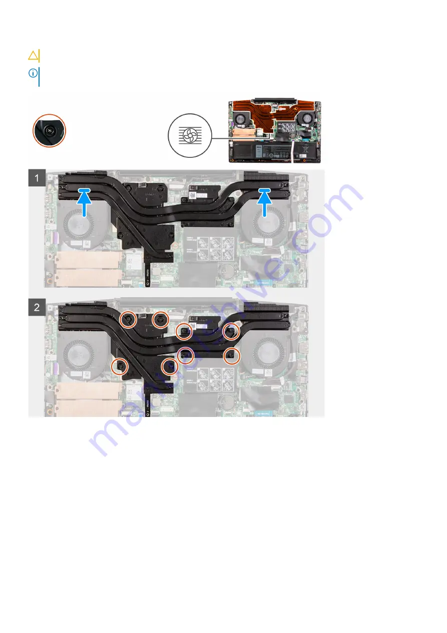
1. Place the heat sink on the system board and align the screw holes on the heat sink with the screw holes on the system board.
2. In reverse sequential order (8>7>6>5>4>3>2>1), tighten the eight captive screws that secure the heat sink to the system board.
Next steps
1. Install the
.
2. Follow the procedure in
After working inside your computer
.
Removing and installing components
41
Summary of Contents for G3 3500
Page 1: ...G3 3500 Service Manual Regulatory Model P89F Regulatory Type P89F002 ...
Page 12: ...12 Removing and installing components ...
Page 14: ...14 Removing and installing components ...
Page 24: ...24 Removing and installing components ...
Page 48: ...48 Removing and installing components ...
Page 78: ...Function key Behavior Page up Page down Home End 78 Troubleshooting ...


