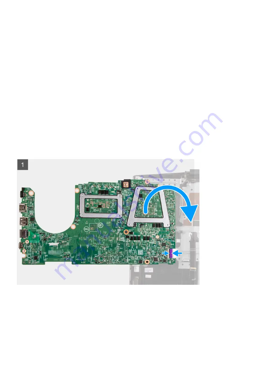
Steps
1. Open the latch, and disconnect the display cable from the system board.
2. Open the latch, and disconnect the keyboard-backlight cable (optional) from the system board.
3. Open the latch, and disconnect the fingerprint-reader cable (optional) from the system board.
4. Open the latch, and disconnect the touchpad cable from the system board.
5. Open the latch, and disconnect the battery cable from the system board.
6. Open the latch, and disconnect the keyboard-backlight cable (optional) from the system board.
7. Open the latch, and disconnect the keyboard cable from the system board.
8. Disconnect the speaker cable from the system board.
9. Remove the two (M2x2) screws that secure the system board to the palm-rest and keyboard assembly.
10. Turn the system board over, and disconnect the I/O board cable from the system board.
Installing the system board
Prerequisites
If your are replacing a component, remove the existing component before performing the installation procedure.
About this task
The following image indicates the location of the system board and provides a visual representation of the installation procedure.
Removing and installing components
49
Summary of Contents for G3 3500
Page 1: ...G3 3500 Service Manual Regulatory Model P89F Regulatory Type P89F002 ...
Page 12: ...12 Removing and installing components ...
Page 14: ...14 Removing and installing components ...
Page 24: ...24 Removing and installing components ...
Page 48: ...48 Removing and installing components ...
Page 78: ...Function key Behavior Page up Page down Home End 78 Troubleshooting ...


