background image

ALERT! Cover  was previously  removed.

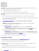
10.  Reset the chassis intrusion detector by changing 

Chassis Intrusion

 to 

Enabled 

or

 Enabled-Silent

NOTE: 

If a setup password has been assigned by someone else, contact your network administrator for

information on resetting the chassis intrusion detector.

Back to Contents Page


Summary of Contents for GX260 - Optiplex Pentium 4 2.0GHz 512MB 40GB CD

Page 1: ...Attaching and Removing the Computer Stand Adding and Removing Parts Opening the Computer Cover AGP and DVI Adapter Cards Battery Memory PCI Cards and Serial Port Adapters Drives Microprocessor Telephony Applications Programming Interface TAPI Closing the Computer Cover Small Desktop Computer About Your Computer Front View Back View Inside Your Computer Attaching and Removing the Computer Stand Add...

Page 2: ...e list of abbreviations and acronyms see the Glossary If you purchased a Dell n Series computer any references in this document to Microsoft Windows operating systems are not applicable Information in this document is subject to change without notice 2001 2002 Dell Computer Corporation All rights reserved Reproduction in any manner whatsoever without the written permission of Dell Computer Corpora...

Page 3: ...is document to refer to either the entities claiming the marks and names or their products Dell Computer Corporation disclaims any proprietary interest in trademarks and trade names other than its own Models DHS DHP and DHM December 2002 2N427 Rev A03 ...

Page 4: ...tion ResourceCD You can use this CD to access documentation reinstall drivers or run diagnostics tools How to set up my computer Troubleshooting information Tools and utilities Warranty information Setup and Quick Reference Guide Express Service Code and Service Tag Number Microsoft Windows License Label Express Service Code and Product Key Located on your computer How to reinstall my operating sy...

Page 5: ...with other Dell customers Upgrades upgrade information for components such as memory the hard drive and the operating system Customer Care contact information order status warranty and repair information Downloads drivers patches and software updates Reference computer documentation product specifications and white papers Service call status Top technical issues for my computer Frequently asked qu...

Page 6: ......

Page 7: ...M 2 2 2 6 GHz processors 512 KB SRAM Certain 2 0G systems may be upgraded to 512K cache Math coprocessor internal to microprocessor Memory Architecture 200 and 266 megahertz MHz double data rate DDR synchronous dynamic random access memory SDRAM Dual in line memory module DIMM sockets two non error checking and correction non ECC DIMM capacities 128 256 512 MB and 1 GB Minimum random access memory...

Page 8: ...e AGP slot half length cards are supported card size 10 67 cm 4 2 inches high by 17 65 cm 6 95 inches long Small mini tower computer expansion card connectors four PCI slots and one AGP slot card sizes three PCI slots support cards up to 27 9 cm 11 inches long and one PCI slot and the AGP slot support cards up to 22 9 cm 9 inches long PCI expansion card connector size 120 pins PCI expansion card c...

Page 9: ...cessible Primary IDE hard drive 40 pin connector on PCI local bus Secondary IDE hard drive 40 pin connector on PCI local bus Floppy drive 34 pin connector CD drive audio interface 4 pin connector Telephony 4 pin connector Fan 3 pin connector PCI 120 pin connector Key Combinations Ctrl Alt Del restarts reboots the computer Ctrl Alt toggles microprocessor speeds on 101 key keyboard in MS DOS real mo...

Page 10: ...ply Wattage small form factor computer 160 W small desktop computer 180 W small mini tower computer 250 W Heat dissipation small form factor computer 455 BTU hr average small desktop computer 500 BTU hr average small mini tower computer 910 BTU hr average Voltage 90 to 135 V at 50 60 Hz 180 to 265 V at 50 60 Hz Backup battery 3 V CR2032 lithium coin cell Physical Small form factor computer Height ...

Page 11: ...to 200 Hz at 0 5 octave min Storage 0 5 G at 3 to 200 Hz at 1 octave min Maximum shock Operating bottom half sine pulse with a change in velocity of 20 inches sec 50 8 cm sec Storage 27 G faired square wave with a velocity change of 200 inches sec 508 cm sec Altitude Operating 16 to 3048 m 50 to 10 000 ft Storage 16 to 10 600 m 50 to 35 000 ft Back to Contents Page ...

Page 12: ...ector MODEM 3 battery socket BATTERY 14 power connector 12VPOWER 4 CD DVD drive connector IDE2 15 second serial connector SER2 5 hard drive connector IDE1 16 microprocessor and heat sink connector CPU 6 front panel connector FRONTPANEL 17 memory module connectors DIMM A and DIMM B 7 PCI riser small mini tower computer only 18 microprocessor fan connector FAN 8 standby power light AUX_PWR 19 power ...

Page 13: ...9 AGP card connector AGP 20 RTC reset jumper RTCRST 10 PCI card connectors PCI1 PCI2 PCI3 and PCI4 21 password jumper PSWD 11 front panel audio cable connector FRONTAUDIO Back to Contents Page ...

Page 14: ...ntiglare coating To clean your monitor screen lightly dampen a soft clean cloth with water If possible use a special screen cleaning tissue or solution suitable for the monitor s antistatic coating Wipe the keyboard computer and plastic part of the monitor with a soft cleaning cloth moistened with a solution of three parts water and one part liquid dishwashing detergent Wipe off stubborn stains wi...

Page 15: ...tion CDs and DVDs 1 Hold the disc by its outer edge It is okay to touch the inside edge of the center hole NOTICE To prevent damaging the surface do not wipe in a circular motion around the disc 2 With a soft lint free cloth gently wipe the bottom of the disc the unlabeled side in a straight line from the center to the outer edge of the disc For stubborn dirt try using water or a diluted solution ...

Page 16: ...ating system or operating system absent alerting techniques It is designed to generate an alert on potential security and fault conditions when the operating system is in a sleep state or the system is powered down ASF is designed to supercede previous operating system absent alerting technologies The OptiPlex GX260 supports the following ASF alerts and remote capabilities Alert Description Chassi...

Page 17: ...lert when a chassis has been compromised or a potential problem has been detected Used in conjunction with IT Assistant OMCI allows customers to remotely perform remote BIOS updates and modify CMOS settings on a single Dell system or a group of Dell systems For information about Dell OpenManage Client Instrumentation see the Dell OpenManage Client Instrumentation User s Guide available on the Dell...

Page 18: ...ity for the data on your computer they are not foolproof If your data requires more security it is your responsibility to obtain and use additional forms of protection such as data encryption programs System Password NOTICE If you leave your computer running and unattended without having a system password assigned or if you leave your computer unlocked so that someone can disable the password by c...

Page 19: ...g prompts appears on the screen If Password Status is set to Unlocked Type in the password and press ENTER to leave password security enabled press CTRL ENTER to disable password security Enter password If Password Status is set to Locked Type the password and press Enter If you have assigned a setup password the computer accepts your setup password as an alternate system password If you type a wr...

Page 20: ...the system password cannot be used in place of the setup password 1 Enter system setup see System Setup and verify that Setup Password is set to Not Enabled 2 Highlight Setup Password and press the left or right arrow key The computer prompts you to type and verify the password If a character is not permitted the computer emits a beep 3 Type and then verify the password After you verify the passwo...

Page 21: ... jumper 3 Close the computer cover 4 Reconnect your computer and devices to electrical outlets and turn them on This disables the existing password s 5 Enter system setup and verify that Setup Password is set to Disabled 6 Exit system setup CAUTION Before you open the computer cover see CAUTION Safety Instructions 7 Open the computer cover 8 Replace the PSWD jumper plug 9 Close the computer cover ...

Page 22: ...or your computer Information on the screen is organized into four areas Title The box at the top of all screens that lists the computer name Computer data Two boxes below the title box that display your computer processor L2 cache service tag and the version number of the BIOS Options A scrollable box listing options that define the configuration of your computer including installed hardware power...

Page 23: ...The computer attempts to boot from the CD drive If no CD is in the drive or if the CD has no operating system the computer generates an error message PXE As the computer boots press F3 to display a menu that allows you to select a method for booting from a network server If a boot routine is not available from the network server the system attempts to boot from the next device in the boot sequence...

Page 24: ...gned Auto Power On Sets time and days of week to turn on the computer automatically Choices are every day or every Monday through Friday Time is kept in a 24 hour format hours minutes Change the start up time by pressing the right or left arrow keys to increase or decrease the numbers or type numbers in both the date and time fields Disabled is the default This feature does not work if you turn of...

Page 25: ...address 3F8h which shares IRQ4 with COM3 is remapped to COM3 I O address 3E8h COM2 I O address 2F8h which shares IRQ3 with COM4 is remapped to COM4 I O address 2E8h NOTE When two COM connectors share an IRQ setting you can use either connector as necessary but you may not be able to use them both at the same time If you are running the Windows 95 or IBM OS 2 operating system you cannot use both se...

Page 26: ... the primary IDE interface if you have an IDE device connected to the secondary IDE interface If You Have a Problem If the computer generates a drive error message the first time you boot your computer after you install an IDE drive your drive may not work with the automatic drive type detect feature Press Alt d in any hard drive field to set the hard drive autoconfiguration feature During POST th...

Page 27: ...ter shutdown when possible You can use the ACPI feature to configure the function of the Windows 2000 and Windows XP operating systems Power Button Functions for Windows 2000 and Windows XP With ACPI Enabled Action Results Computer Turned On and ACPI Enabled Computer in Standby Mode Computer Turned Off Press power button Computer goes into standby mode or turns off depending on the operating syste...

Page 28: ... unplug the AC power cable from the computer wait for the computer to completely stop running and plug in the AC power cable If the computer does not restart press the power button to restart the computer Hyper Threading Hyper Threading is an Intel technology that can enhance overall performance by allowing one physical microprocessor to function as two logical microprocessors capable of performin...

Page 29: ......

Page 30: ...es such as your CD player are operating 4 power button Press this button to turn on the computer NOTICE To avoid losing data do not use the power button to turn off the computer Instead perform a Microsoft Windows shutdown 5 power light The power light illuminates and blinks or remains solid to indicate different states No light The computer is in the off state S4 S5 or mechanical OFF Steady green...

Page 31: ... position even though the AC power available in Japan is 100 V Also ensure that your monitor and attached devices are electrically rated to operate with the AC power available in your location Back Panel 1 parallel connector Connect a parallel device such as a printer to the parallel connector If you have a USB printer plug it into a USB connector NOTE The integrated parallel connector is automati...

Page 32: ...back device such as a cassette player CD player or VCR On computers with a sound card the line in connector is on the card 9 microphone connector Use the pink microphone connector available on computers with integrated sound to attach a personal computer microphone for voice or musical input into a sound or telephony program On computers with a sound card the microphone connector is on the card 10...

Page 33: ...lower assembly 5 chassis intrusion switch Cable Colors Hard drive Blue pull tab Floppy drive Black pull tab CD DVD drive Orange pull tab Attaching and Removing the Computer Stand The computer can be used in either a vertical or horizontal position To use the computer in a vertical position you must attach the computer stand ...

Page 34: ... button on the side of the cover and aligning the captive screw in the stand with the screw hole in the cover b When the stand is in place tighten the thumbscrew 3 Rotate the computer so that the stand is at the bottom and the drives are at the top Computer Stand To remove the computer stand 1 Turn the computer over so that the stand is at the top 2 Loosen the thumbscrew and lift the stand away 3 ...

Page 35: ...Parts Dell OptiPlex GX260 Systems User s Guide Opening the Computer Cover AGP and DVI Adapter Cards Battery Drives Memory Microprocessor PCI Cards and Serial Port Adapters Telephony Applications Programming Interface TAPI Closing the Computer Cover Back to Contents Page ...

Page 36: ...ect them from their electrical outlets 3 Disconnect the computer power cable from the wall outlet and then press the power button to ground the system board 4 Remove the computer stand if it is attached 5 If you have installed a padlock through the padlock ring on the back panel remove the padlock NOTICE Ensure that there is sufficient space to support the open cover at least 30 cm 1 ft of desktop...

Page 37: ...Back to Contents Page ...

Page 38: ...raphics driver s user interface icon 1 Perform an orderly computer shutdown using the operating system menu NOTICE To disconnect a network cable first unplug the cable from your computer and then unplug it from the network wall jack 2 Turn off any attached devices and disconnect them from their electrical outlets 3 Disconnect the computer power cable from the wall outlet and then press the power b...

Page 39: ...er cover 5 Attach the computer stand optional NOTICE To connect a network cable first plug the cable into the network wall jack and then plug it into the computer 6 Connect the monitor cable to the card s video connector 7 Connect your computer and devices to their electrical outlets and turn them on After you open and close the cover the chassis intrusion detector if enabled causes the following ...

Page 40: ...information on resetting the chassis intrusion detector Back to Contents Page ...

Page 41: ...on information is erased if the computer is turned off or unplugged from the electrical outlet In this case you must enter system setup and reset the configuration options CAUTION A new battery can explode if it is incorrectly installed Replace the battery only with the same or equivalent type recommended by the manufacturer Discard used batteries according to the manufacturer s instructions 1 If ...

Page 42: ...he following message to appear on the screen at the next computer start up ALERT Cover was previously removed 8 Reset the chassis intrusion detector by changing Chassis Intrusion to Enabled or Enabled Silent NOTE If a setup password has been assigned by someone else contact your network administrator for information on resetting the chassis intrusion detector 9 Access system setup and restore the ...

Page 43: ... NOTICE To disconnect a network cable first unplug the cable from your computer and then unplug it from the network wall jack 2 Turn off any attached devices and disconnect them from their electrical outlets 3 Disconnect the computer power cable from the wall outlet and then press the power button to ground the system board 4 If your computer has a stand and it is attached remove the stand 5 Open ...

Page 44: ... the ends of the module until it snaps into place If you insert the module correctly the securing clips snap into the cutouts at each end of the module 4 Close the computer cover 5 If your computer uses a computer stand attach the stand NOTICE To connect a network cable first plug the cable into the network wall jack and then plug it into the computer 6 Connect your computer and devices to electri...

Page 45: ...ystem Memory to reflect the newly installed memory Verify the new total If it is correct skip to step 10 9 If the memory total is incorrect turn off and disconnect your computer and devices from their electrical outlets Open the computer cover and check the installed memory modules to ensure that they are seated properly in their sockets Then repeat steps 4 5 and 6 10 When the System Memory total ...

Page 46: ...the procedures in the next section If you are removing but not replacing a PCI card skip to Removing a PCI Card Installing a PCI Card CAUTION Before you perform this procedure see CAUTION Safety Instructions 1 If you are replacing a card remove the current driver for the card from the operating system 2 Perform an orderly computer shutdown using the operating system menu NOTICE To disconnect a net...

Page 47: ...the card making internal connections or otherwise customizing it for your computer CAUTION Some network adapters automatically start the computer when they are connected to a network To guard against electrical shock be sure to unplug your computer from its electrical outlet before installing any cards Verify that the standby power light on the system board is off To locate this light see System B...

Page 48: ...rd 12 Before you lower the retention arm ensure that The tops of all cards and filler brackets are flush with the alignment bar The notch in the top of the card or filler bracket fits around the alignment guide Press the arm into place securing the card s in the computer Closing the Retention Arm ...

Page 49: ...on resetting the chassis intrusion detector 16 If you installed a sound card a Enter system setup select Integrated Devices and change the setting for Sound to Off b Connect external audio devices to the sound card s connectors Do not connect external audio devices to the microphone speaker headphone or line in connectors on the I O panel 17 If you installed an add in network adapter a Enter syste...

Page 50: ...or if enabled causes the following message to appear on the screen at the next computer start up ALERT Cover was previously removed 12 Reset the chassis intrusion detector by changing Chassis Intrusion to Enabled or Enabled Silent NOTE If a setup password has been assigned by someone else contact your network administrator for information on resetting the chassis intrusion detector 13 Remove the c...

Page 51: ...ide see Closing the Retention Arm 9 Attach the serial card cable to the connector on the system board labeled SER2 Installing a Serial Port Adapter 1 SER2 system board connector 2 card bracket 3 serial card cable 4 card slot opening 10 Lower the retention arm into place securing the card s in the computer see Closing the Retention Arm Removing a Serial Port Adapter CAUTION Before you perform this ...

Page 52: ...cket in the empty card slot opening If you need a filler bracket contact Dell NOTE Installing filler brackets over empty card slot openings is necessary to maintain FCC certification of the computer The brackets also keep dust and dirt out of your computer 10 Lower the retention arm and press it into place NOTICE To connect a network cable first plug the cable into the network wall jack and then p...

Page 53: ...a single IDE interface cable and configure them for the cable select setting the device attached to the last connector on the interface cable is the master or boot device drive 0 and the device attached to the middle connector on the interface cable is the slave device drive 1 See the drive documentation in your upgrade kit for information on configuring devices for the cable select setting Your c...

Page 54: ...e on the other connector Keyed connectors ensure that the pin 1 wire in the cable indicated by the colored stripe along one edge of the cable goes to the pin 1 end of the connector The pin 1 end of a connector on a board or a card is usually indicated by a silk screened 1 printed directly on the board or card NOTICE When you connect an interface cable do not place the colored stripe away from pin ...

Page 55: ... surface on the chassis such as the metal around the card slot openings at the back of the computer before touching anything inside your computer While you work periodically touch an unpainted metal surface on the computer chassis to dissipate any static electricity that might harm internal components NOTICE To disconnect a network cable first unplug the cable from your computer and then unplug it...

Page 56: ...1 power cable 2 hard drive cable 2 Press in on the tabs on each side of the drive and slide the drive toward the I O panel and remove it from the computer Removing the Hard Drive ...

Page 57: ...y aligning the screw holes on the drive with the screw holes on the bracket rails and then inserting and tightening all four screws two screws on each rail Hard Drive Bracket Rails 1 drive 2 bracket rails 2 3 screws 4 3 Install the hard drive into the computer by gently sliding the drive into place until you hear it securely click NOTICE Match the colored strip on the cable with pin 1 on the drive...

Page 58: ...nstalled is the primary drive insert a bootable floppy disk into drive A 10 Turn on the computer 11 Enter system setup and update the appropriate Primary Drive option 0 or 1 12 Exit system setup and reboot the computer 13 Partition and logically format your drive before you proceed to the next step For instructions see the documentation that came with your operating system 14 Test the hard drive b...

Page 59: ...e electrical outlet before opening the cover 1 Perform an orderly computer shutdown using the operating system menu 2 Turn off your computer and any attached devices 3 Ground yourself by touching an unpainted metal surface on the chassis such as the metal around the card slot openings at the back of the computer before touching anything inside your computer While you work periodically touch an unp...

Page 60: ...wer cable from the CD DVD drive 4 Remove or raise the drive by pressing the green tabs on either side of the drive and lifting the drive up 5 Remove the floppy drive cable from the floppy drive a Remove the interposer board from the floppy drive by pressing the tab and rotating the interposer board Removing the Interposer Board 1 floppy drive cable 2 tab 3 interposer board 4 system board floppy dr...

Page 61: ...1 floppy drive cable 2 lever 6 Remove the floppy drive from its sled by pulling the sled tab out while pushing the drive up and then sliding the drive out of the sled Removing the Floppy Drive ...

Page 62: ... drive a Slide the floppy drive cable into the connector b Close the lever so that the cable is secure in the connector c Line up the hole on the bottom of the interposer board with the notch on the connector and snap the interposer board onto the drive 3 Gently slide the drive into the computer until the tabs securely click into position Attaching the Floppy Drive Cable ...

Page 63: ...e floppy drive 5 Attach the CD DVD drive cable and the power cable to the CD DVD drive 6 Connect the floppy drive cable to the DSKT connector on the system board 7 Check all cable connections and fold cables out of the way to provide airflow for the fan and cooling vents 8 Close the computer cover and attach the computer stand optional ...

Page 64: ...res in this section follow the steps in CAUTION Safety Instructions CAUTION To guard against electrical shock always unplug your computer from the electrical outlet before opening the cover 1 Perform an orderly computer shutdown using the operating system menu 2 Turn off your computer and any devices 3 Ground yourself by touching an unpainted metal surface on the chassis such as the metal around t...

Page 65: ... interposer board from the drive Removing the Interposer Board 1 interposer board 3 Press inward on the two tabs on the sides of the drive and then slide the drive upward and remove it from the drive bay Installing a CD DVD Drive 1 Unpack the drive and prepare it for installation ...

Page 66: ...ting 2 Gently slide the drive into place until the tabs securely click into position 3 Connect the interposer board to the CD drive a Ensure that the interposer board tab fits securely under the notch on the inside of the cover b Attach the power and audio cables to the interposer board Connecting the Interposer Board 1 interposer board 2 notch on inside of cover 3 interposer board tab ...

Page 67: ...evices to their electrical outlets and turn them on See the documentation that came with the drive for instructions on installing any software required for drive operation 10 Update your configuration information by setting the appropriate Drive option 0 or 1 under Drives Secondary to Auto See Primary Drive n and Secondary Drive n for more information After you open and close the cover the chassis...

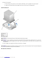
Page 68: ...m their electrical outlets 3 Disconnect the computer power cable from the wall outlet and then press the power button to ground the system board 4 Remove the computer stand if it is attached 5 Open the computer cover 6 Disconnect the cooling fan power cable from the FAN connector on the system board 7 Disconnect the 12 volt power cable from the 12VPOWER connector on the system board 8 Remove the h...

Page 69: ...ssor upgrade kit from Dell discard the original heat sink If you are not installing a microprocessor upgrade kit from Dell reuse the original heat sink when you install your new microprocessor NOTICE Be careful not to bend any of the pins when you remove the microprocessor Bending the pins can permanently damage the microprocessor 11 Pull the release lever straight up until the microprocessor is r...

Page 70: ...ICE Be careful not to bend any of the pins when you unpack the microprocessor Bending the pins can permanently damage the microprocessor 12 Unpack the new microprocessor If any of the pins on the microprocessor appear to be bent contact Dell see Getting Help for instructions on obtaining technical assistance Microprocessor Installation ...

Page 71: ... it 16 When the microprocessor is fully seated in the socket pivot the release lever back toward the socket until it snaps into place to secure the microprocessor NOTICE Ground yourself by touching an unpainted metal surface on the back of the computer NOTICE If you are not installing a microprocessor upgrade kit from Dell reuse the original blower heat sink assembly when you replace the microproc...

Page 72: ...the computer 24 Connect your computer and devices to electrical outlets and turn them on After you open and close the cover the chassis intrusion detector if enabled causes the following message to appear on the screen at the next computer start up ALERT Cover was previously removed 25 Reset the chassis intrusion detector by changing the Chassis Intrusion option to Enabled or Enabled Silent NOTE I...

Page 73: ......

Page 74: ...ng a TAPI Compliant Modem Card 1 Perform an orderly computer shutdown using the operating system menu NOTICE To disconnect a network cable first unplug the cable from your computer and then unplug it from the network wall jack 2 Turn off any attached devices and disconnect them from their electrical outlets 3 Disconnect the computer power cable from the wall outlet and then press the power button ...

Page 75: ... microphone speaker headphone or line in connectors on the front or back panel of your computer 8 Connect the 4 pin TAPI cable to the TAPI sound card connector To locate the TAPI connector on the sound card see the manufacturer s documentation 9 Connect the other end of the cable to the TAPI connector on the modem card To locate the TAPI connector on the card see the manufacturer s documentation 1...

Page 76: ......

Page 77: ...f the cover are locked If not repeat this step NOTICE To connect a network cable first plug the cable into the network wall jack and then plug it into the computer 4 Connect your computer and devices to electrical outlets and turn them on After you open and close the cover the chassis intrusion detector if enabled causes the following message to appear on the screen at the next computer start up A...

Page 78: ... drive light button The floppy drive light is on when the computer reads data from or writes data to the floppy drive Wait until this light turns off before you remove the floppy disk from the drive 4 hard drive light The hard drive light is on when the computer reads data from or writes data to the hard drive The light might also be on when devices such as your CD player are operating 5 power but...

Page 79: ...ll technical support 10 headphone connector Attach headphones 11 USB connectors Connect USB devices such as a mouse keyboard printer joystick and computer speakers into any of the USB connectors Back View Small Desktop Computer 1 back panel connectors The connectors for your computer 2 AGP DVI card slot The slot for an AGP or DVI adapter card 3 card slots The slot for PCI cards or a second serial ...

Page 80: ...ter is not detecting a physical connection to the network 5 network adapter Attach the UTP cable to an RJ45 jack wall plate or to an RJ45 port on a UTP concentrator or hub and press the other end of the UTP cable into the network adapter connector until the cable snaps securely into place Dell recommends the use of Category 5 wiring and connectors for our customers networks 6 network activity ligh...

Page 81: ...evice to that connector For more information see System Setup Options Inside Your Computer CAUTION Before you begin any of the procedures in this section follow the steps in CAUTION Safety Instructions CAUTION To avoid electrical shock always unplug your computer from the electrical outlet before opening the cover NOTICE Be careful when opening the computer cover to ensure that you do not accident...

Page 82: ...ace the computer on its right side so that the drive bays are at the bottom 2 Fit the stand onto what was the left side of the computer a Position the stand as shown in the following illustration by aligning the large round hole in the stand with the securing button on the side of the cover and aligning the captive screw in the stand with the screw hole in the cover b When the stand is in place ti...

Page 83: ...To remove the stand 1 Turn the computer over so that the stand is at the top 2 Loosen the thumbscrew and lift the stand away 3 Place the computer in a horizontal position Back to Contents Page ...

Page 84: ...rts Dell OptiPlex GX260 Systems User s Guide Opening the Computer Cover AGP and DVI Adapter Cards Battery Drives Memory Microprocessor PCI Cards and Serial Port Adapters Telephony Applications Programming Interface TAPI Closing the Computer Cover Back to Contents Page ...

Page 85: ...ttached devices and disconnect them from their electrical outlets 3 Disconnect the computer power cable from the wall outlet and then press the power button to ground the system board 4 Remove the computer stand if it is attached 5 If you have installed a padlock through the padlock ring on the back panel remove the padlock NOTICE Ensure that there is sufficient space to support the open cover at ...

Page 86: ...2 padlock ring 3 two release buttons one on each side Back to Contents Page ...

Page 87: ...egrated graphics driver s user interface icon 1 Perform an orderly computer shutdown using the operating system menu 2 Turn off any attached devices and disconnect them from their electrical outlets NOTICE To disconnect a network cable first unplug the cable from your computer and then unplug it from the network wall jack 3 Disconnect the computer power cable from the wall outlet and then press th...

Page 88: ...nged lever 2 indented tab side view 2 Press the card clip lever toward the PCI slot and remove the installed card Removing the Card 1 card notch 2 card clip lever 3 card clip tab 4 card clip 5 PCI card slot ...

Page 89: ...rst plug the cable into the network wall jack and then plug it into the computer 6 Connect the monitor cable to the card s video connector 7 Connect your computer and devices to electrical outlets and turn them on After you open and close the cover the chassis intrusion detector if enabled causes the following message to appear on the screen at the next computer start up ALERT Cover was previously...

Page 90: ...drive 3 hard drive IDE Drive Addressing When you connect two IDE devices to a single IDE interface cable and configure them for the cable select setting the device attached to the last connector on the interface cable is the master or boot device drive 0 and the device attached to the middle connector on the interface cable is the slave device drive 1 See the drive documentation in your upgrade ki...

Page 91: ...face connectors are keyed for correct insertion that is a notch or a missing pin on one connector matches a tab or a filled in hole on the other connector Keyed connectors ensure that the pin 1 wire in the cable indicated by the colored stripe along one edge of the cable goes to the pin 1 end of the connector The pin 1 end of a connector on a board or a card is usually indicated by a silk screened...

Page 92: ...ssis to dissipate any static electricity that might harm internal components NOTICE To disconnect a network cable first unplug the cable from your computer and then unplug it from the network wall jack 5 Disconnect your computer and devices from their power sources Also disconnect any telephone or telecommunication lines from the computer 6 Disconnect the computer power cable from the wall outlet ...

Page 93: ...puter without a hard drive shroud does not affect its performance 2 Disconnect the power and hard drive cables from the drive Removing Power and Drive Cables 1 hard drive cable 2 power cable 3 Press in on the tabs on each side of the drive and slide the drive up and out Removing the Hard Drive ...

Page 94: ...tly cushion it 2 Unpack the replacement hard drive and prepare it for installation 3 If your replacement hard drive does not have the bracket rails attached remove the rails from the old drive by removing the two screws that secure each rail to the drive Attach the bracket rails to the new drive by aligning the screw holes on the drive with the screw holes on the bracket rails and then inserting a...

Page 95: ...ud replace the shroud by inserting the two tabs on the bottom into the holes in the computer and snapping the top into place Operating the computer without a hard drive shroud does not affect its performance 8 Close the computer cover 9 Attach the computer stand optional NOTICE To connect a network cable first plug the cable into the network wall jack and then plug it into the computer 10 Connect ...

Page 96: ...h your operating system After you open and close the cover the chassis intrusion detector if enabled causes the following message to appear on the screen at the next computer start up ALERT Cover was previously removed 18 Reset the chassis intrusion detector by changing Chassis Intrusion to Enabled or Enabled Silent NOTE If a setup password has been assigned by someone else contact your network ad...

Page 97: ...e computer before touching anything inside your computer While you work periodically touch an unpainted metal surface on the computer chassis to dissipate any static electricity that might harm internal components NOTICE To disconnect a network cable first unplug the cable from your computer and then unplug it from the network wall jack 4 Disconnect your computer and devices from their power sourc...

Page 98: ...ables from the back of the floppy drive 3 Disconnect the floppy drive cable from the system board connector labeled DSKT Removing Power and Drive Cables 1 power cable 2 floppy drive cable 3 floppy drive connector DSKT 4 Press inward on the two tabs on the sides of the drive slide the drive upward and remove it from the floppy drive bay Floppy Drive Removal ...

Page 99: ...e drive with the screw holes on the bracket rails and then inserting and tightening all four screws two screws on each rail Floppy Drive Bracket Rails 1 drive 2 bracket rails 2 3 screws 4 2 Gently slide the drive into place until the tabs securely click into position 3 Attach the power and floppy drive cables to the floppy drive 4 Connect the other end of the floppy drive cable to the connector la...

Page 100: ...the documentation that came with the drive for instructions on installing any software required for drive operation 10 Enter system setup and update the appropriate Diskette Drive A option to reflect the size and capacity of your new floppy drive After you open and close the cover the chassis intrusion detector if enabled causes the following message to appear on the screen at the next computer st...

Page 101: ...e any static electricity that might harm internal components NOTICE To disconnect a network cable first unplug the cable from your computer and then unplug it from the network wall jack 4 Disconnect your computer and devices from their power sources Also disconnect any telephone or telecommunication lines from the computer 5 Disconnect the computer power cable from the wall outlet and then press t...

Page 102: ...1 power cable 2 audio cable 3 CD DVD drive cable 4 IDE2 connector 3 Press inward on the two tabs on the sides of the drive and then slide the drive upward and remove it from the drive bay ...

Page 103: ...oving the two screws that secure each rail to the drive Attach the bracket to the new drive by aligning the screw holes on the drive with the screw holes on the bracket rails and then inserting and tightening all four screws two screws on each rail CD DVD Drive Bracket Rails 1 drive 2 bracket rails 2 3 screws 4 3 Gently slide the drive into place until the tabs securely click into position 4 Conne...

Page 104: ...and then plug it into the computer 11 Connect your computer and devices to their electrical outlets and turn them on See the documentation that came with the drive for instructions on installing any software required for drive operation 12 Update your configuration information by setting the appropriate Drive option 0 or 1 under Drives Secondary to Auto See Primary Drive n and Secodary Drive n for...

Page 105: ...has been assigned by someone else contact your network administrator for information on resetting the chassis intrusion detector 14 Verify that your computer works correctly by running the Dell Diagnostics Back to Contents Page ...

Page 106: ...from the wall outlet and then press the power button to ground the system board 4 Remove the computer stand if it is attached 5 Open the computer cover 6 Disconnect the cooling fan power cable from the FAN connector on the system board 7 Disconnect the 12 volt power cable from the 12VPOWER connector on the system board NOTICE Before you remove the heat sink gently rock the heat sink and then sligh...

Page 107: ...ssor upgrade kit from Dell discard the original heat sink If you are not installing a microprocessor upgrade kit from Dell reuse the original heat sink when you install your new microprocessor NOTICE Be careful not to bend any of the pins when you remove the microprocessor Bending the pins can permanently damage the microprocessor 11 Pull the release lever straight up until the microprocessor is r...

Page 108: ...uter NOTICE Be careful not to bend any of the pins when you unpack the microprocessor Bending the pins can permanently damage the microprocessor 12 Unpack the new microprocessor If any of the pins on the microprocessor appear to be bent contact Dell for instructions on obtaining technical assistance Microprocessor Installation ...

Page 109: ...t 16 When the microprocessor is fully seated in the socket pivot the release lever back toward the socket until it snaps into place to secure the microprocessor NOTICE Ground yourself by touching an unpainted metal surface on the back of the computer NOTICE If you are not installing a microprocessor upgrade kit from Dell reuse the original blower heat sink assembly when you replace the microproces...

Page 110: ...the computer 24 Connect your computer and devices to electrical outlets and turn them on After you open and close the cover the chassis intrusion detector if enabled causes the following message to appear on the screen at the next computer start up ALERT Cover was previously removed 25 Reset the chassis intrusion detector by changing the Chassis Intrusion option to Enabled or Enabled Silent NOTE I...

Page 111: ......

Page 112: ...er for the card from the operating system 2 Perform an orderly computer shutdown using the operating system menu NOTICE To disconnect a network cable first unplug the cable from your computer and then unplug it from the network wall jack 3 Turn off any attached devices and disconnect them from their electrical outlets 4 Disconnect the computer power cable from the wall outlet and then press the po...

Page 113: ...1 card cage 2 handle 2 Press the lever on the retention arm and raise the retention arm Raising the Retention Arm and Installing a Card 1 lever 5 card edge connector 2 retention arm 6 card connector ...

Page 114: ...tomatically start the computer when they are connected to a network To guard against electrical shock be sure to unplug your computer from its electrical outlet before installing any cards 3 Insert the card into the card connector If the card is full length insert the end of the card into the card guide bracket as you lower the card toward its connector on the system board Insert the card firmly i...

Page 115: ...en assigned by someone else contact your network administrator for information on resetting the chassis intrusion detector 12 If you installed a sound card a Enter system setup select Integrated Devices and change the setting for Sound to Off b Connect external audio devices to the sound card s connectors Do not connect external audio devices to the microphone speaker headphone or line in connecto...

Page 116: ...board 4 Remove the computer stand if it is attached 5 Open the computer cover 6 Remove the card cage a Check any cables connected to cards through the back panel openings Disconnect any cables that will not reach the card cage once the cage is removed from the computer b Gently pull the handle and lift the card cage up and away from the computer Removing the Card Cage 1 card cage 2 handle 7 Press ...

Page 117: ...lide the adapter bracket down over the card slot opening and lower the retention arm securing the adapter bracket 10 Route the serial card cable under the card cage and attach the cable to the connector on the system board labeled SER2 Replacing the Card Cage and Connecting the Cable ...

Page 118: ...If a setup password has been assigned by someone else contact your network administrator for information on resetting the chassis intrusion detector Removing a Serial Port Adapter CAUTION Before you begin any of the procedures in this section follow the steps in CAUTION Safety Instructions CAUTION To guard against electrical shock always unplug your computer from the electrical outlet before openi...

Page 119: ... a filler bracket in the empty card slot opening If you need a filler bracket contact Dell NOTE Installing filler brackets over empty card slot openings is necessary to maintain FCC certification of the computer The brackets also keep dust and dirt out of your computer 10 Lower the retention arm and press it into place NOTICE To connect a network cable first plug the cable into the network wall ja...

Page 120: ...ector by changing Chassis Intrusion to Enabled or Enabled Silent If a setup password has been assigned by someone else contact your network administrator for information on resetting the chassis intrusion detector Back to Contents Page ...

Page 121: ...ive eject button Press this button to eject a disk from the floppy drive 4 hard drive light The hard drive light is on when the computer reads data from or writes data to the hard drive The light might also be on when devices such as your CD player are operating 5 power button and power light Press this button to turn on the computer NOTICE To avoid losing data do not use the power button to turn ...

Page 122: ... USB connectors Connect USB devices such as a mouse keyboard printer joystick and computer speakers into any of the USB connectors 9 headphone connector Attach headphones 10 Microsoft Windows license label The Windows license label provides the product key for your copy of the Windows operating system You need this information if you reinstall Windows Back View Small Mini Tower Computer 1 power co...

Page 123: ...ctor 3 mouse connector Plug a standard mouse into the green mouse connector Turn off the computer and any attached devices before you connect a mouse to the computer If you have a USB mouse plug it into a USB connector If your computer is running Windows 2000 or Windows XP Dell installed the necessary mouse drivers on your hard drive 4 link integrity light Green A good connection exists between a ...

Page 124: ...f the USB connectors 11 diagnostic lights Use the lights to help you troubleshoot a computer problem based on the diagnostic code For more information see Diagnostic Lights 12 video connector Plug the cable from your VGA compatible monitor into the blue connector 13 serial connector Connect a serial device such as a handheld device to the serial port If you have a second serial connector card inst...

Page 125: ...mbly 2 internal speaker 7 power supply 3 chassis intrusion switch 8 floppy drive 4 system board 9 CD DVD drive 5 padlock ring Cable Colors Hard drive Blue pull tab Floppy drive Black pull tab CD DVD drive Orange pull tab Back to Contents Page ...

Page 126: ...Parts Dell OptiPlex GX260 Systems User s Guide Opening the Computer Cover AGP and DVI Adapter Cards Battery Drives Memory Microprocessor PCI Cards and Serial Port Adapters Telephony Applications Programming Interface TAPI Closing the Computer Cover Back to Contents Page ...

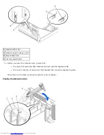
Page 127: ...onnect the computer power cable from the wall outlet and then press the power button to ground the system board 4 If you have installed a padlock through the padlock ring on the back panel remove the padlock NOTICE Ensure that sufficient space exists to support the open cover at least 30 cm 1 ft of desktop space 5 Lay the computer on its side as shown in the illustration 6 Open the cover a Facing ...

Page 128: ...1 release buttons 2 security cable slot 3 padlock ring Back to Contents Page ...

Page 129: ...ontrol Panel and then click the integrated graphics driver s user interface icon 1 Perform an orderly computer shutdown using the operating system menu NOTICE To disconnect a network cable first unplug the cable from your computer and then unplug it from the network wall jack 2 Turn off any attached devices and disconnect them from their electrical outlets 3 Disconnect the computer power cable fro...

Page 130: ...4 card clip 5 PCI card slot AGP Card Insert 1 card notch 2 card clip lever 3 card clip tab 4 card clip 5 PCI card slot Installing an AGP DVI Adapter Card 1 To add or replace the card press the card clip lever toward the PCI card slot and gently press the card into the AGP connector until it clicks into place ...

Page 131: ...e card s video connector 6 Connect your computer and devices to electrical outlets and turn them on After you open and close the cover the chassis intrusion detector if enabled causes the following message to appear on the screen at the next computer start up ALERT Cover was previously removed 7 Reset the chassis intrusion detector by changing Chassis Intrusion to Enabled or Enabled Silent NOTE If...

Page 132: ... interface cable and configure them for the cable select setting the device attached to the last connector on the interface cable is the master or boot device drive 0 and the device attached to the middle connector on the interface cable is the slave device drive 1 See the drive documentation in your upgrade kit for information on configuring devices for the cable select setting Your computer supp...

Page 133: ...on one connector matches a tab or a filled in hole on the other connector Keyed connectors ensure that the pin 1 wire in the cable indicated by the colored stripe along one edge of the cable goes to the pin 1 end of the connector The pin 1 end of a connector on a board or a card is usually indicated by a silk screened 1 printed directly on the board or card NOTICE When you connect an interface cab...

Page 134: ...uching an unpainted metal surface on the chassis such as the metal around the card slot openings at the back of the computer before touching anything inside your computer While you work periodically touch an unpainted metal surface on the computer chassis to dissipate any static electricity that might harm internal components NOTICE To disconnect a network cable first unplug the cable from your co...

Page 135: ...of the drive and slide the drive up and out Removing the Hard Drive 1 tabs 2 2 hard drive Installing a Hard Drive 1 Unpack the replacement hard drive and prepare it for installation 2 Check the documentation for the drive to verify that it is configured for your computer ...

Page 136: ...he screw holes on the bracket rails and then inserting and tightening all four screws two screws on each rail Hard Drive Bracket Rails 1 drive 2 bracket rails 2 3 screws 4 4 Install the hard drive into the computer by gently sliding the drive into place until you hear it securely click NOTICE Match the colored strip on the cable with pin 1 on the drive pin 1 is marked as 1 5 Connect the power and ...

Page 137: ... drive A 10 Turn on the computer 11 Enter system setup and update the appropriate Primary Drive option 0 or 1 12 Exit system setup and reboot the computer 13 Partition and logically format your drive before you proceed to the next step See the documentation for your operating system for instructions 14 Test the hard drive by running the Dell Diagnostics 15 If the drive you just installed is the pr...

Page 138: ...sconnect a network cable first unplug the cable from your computer and then unplug it from the network wall jack 5 Disconnect your computer and devices from their power sources Also disconnect any telephone or telecommunication lines from the computer 6 Disconnect the computer power cable from the wall outlet and then press the power button to ground the system board 7 Open the computer cover 8 Re...

Page 139: ...at is attached to your first hard drive and attach the connector to the second hard drive Your computer uses cable select drive cables This means that the device connected to the end connector of the drive cable is the master device and the device connected to the middle connector is the slave device Be sure that the jumper setting on the new device is set for cable select see the documentation th...

Page 140: ...se the cover the chassis intrusion detector if enabled causes the following message to appear on the screen at the next computer start up ALERT Cover was previously removed 17 Reset the chassis intrusion detector by changing Chassis Intrusion to Enabled or Enabled Silent NOTE If a setup password has been assigned by someone else contact your network administrator for information on resetting the c...

Page 141: ...r Removing the Front Panel Inserts Floppy Drive CAUTION Before you begin any of the procedures in this section follow the steps in CAUTION Safety Instructions CAUTION To guard against electrical shock always unplug your computer from the electrical outlet before ...

Page 142: ...To disconnect a network cable first unplug the cable from your computer and then unplug it from the network wall jack 4 Disconnect your computer and devices from their power sources Also disconnect any telephone or telecommunication lines from the computer 5 Disconnect the computer power cable from the wall outlet and then press the power button to ground the system board 6 Open the computer cover...

Page 143: ...rail to the drive Attach the bracket to the new drive by aligning the screw holes on the drive with the screw holes on the bracket rails and then inserting and tightening all four screws two screws on each rail Floppy Drive Bracket Rails 1 drive 2 bracket rails 2 3 screws 4 2 Gently slide the drive into place until the tabs securely click into position 3 Attach the power and floppy drive cables to...

Page 144: ...ion that came with the drive for instructions on installing any software required for drive operation 9 Enter system setup and update the appropriate Diskette Drive A option to reflect the size and capacity of your new floppy drive After you open and close the cover the chassis intrusion detector if enabled causes the following message to appear on the screen at the next computer start up ALERT Co...

Page 145: ...ng inside your computer While you work periodically touch an unpainted metal surface on the computer chassis to dissipate any static electricity that might harm internal components NOTICE To disconnect a network cable first unplug the cable from your computer and then unplug it from the network wall jack 4 Disconnect your computer and devices from their power sources Also disconnect any telephone ...

Page 146: ...1 power cable 2 audio cable 3 CD DVD drive cable 2 Press inward on the two tabs on the sides of the drive and then slide the drive upward and remove it from the drive bay Installing a CD DVD Drive ...

Page 147: ... you are installing a replacement drive and the new drive does not have the bracket rails attached remove the rails from the old drive by removing the two screws that secure each rail to the drive Attach the bracket to the new drive by aligning the screw holes on the drive with the screw holes on the bracket rails and then inserting and tightening all four screws two screws on each rail CD DVD Dri...

Page 148: ...outlets and turn them on See the documentation that came with the drive for instructions on installing any software required for drive operation 11 Update your configuration information by setting the appropriate Drive option 0 or 1 under Drives Secondary to Auto See Primary Drive n and Secodary Drive n for more information After you open and close the cover the chassis intrusion detector if enabl...

Page 149: ...13 Verify that your computer works correctly by running the Dell Diagnostics Back to Contents Page ...

Page 150: ...stem menu NOTICE To disconnect a network cable first unplug the cable from your computer and then unplug it from the network wall jack 2 Turn off any attached devices and disconnect them from their electrical outlets 3 Disconnect the computer power cable from the wall outlet and then press the power button to ground the system board 4 Open the computer cover 5 Disconnect the cooling fan power cabl...

Page 151: ... solution facing upward NOTICE If you are installing a microprocessor upgrade kit from Dell discard the original heat sink If you are not installing a microprocessor upgrade kit from Dell reuse the original heat sink and blower when you install your new microprocessor 9 Pull the release lever straight up until the microprocessor is released NOTICE Be careful not to bend any of the pins when you re...

Page 152: ...e new microprocessor Installing the Microprocessor NOTICE You must position the microprocessor correctly in the socket to avoid permanent damage to the microprocessor and the computer 1 If the release lever is not extended to the release position move it to that position 2 Align pin 1 the imprinted corner of the microprocessor and pin 1 of the socket Microprocessor Installation ...

Page 153: ...e the release lever back toward the system board until it snaps into place securing the microprocessor 5 Install the heat sink a Insert the notched end of the heat sink onto the end of the retention base that is opposite the hinge b Lower the heat sink until it fits securely in the base 6 Raise the retention lever and press until the heat sink is secured You will feel the lever pause once it is at...

Page 154: ...er cover NOTICE To connect a network cable first plug the cable into the network wall jack and then plug it into the computer 11 Connect your computer and devices to electrical outlets and turn them on After you open and close the cover the chassis intrusion detector if enabled causes the following message to appear on the screen at the next computer start up ALERT Cover was previously removed 12 ...

Page 155: ...Back to Contents Page ...

Page 156: ...edures in the next section If you are removing but not replacing a card see Removing a Card Installing a PCI Card CAUTION Before you perform this procedure see CAUTION Safety Instructions 1 If you are replacing a card remove the current driver for the card from the operating system 2 Perform an orderly computer shutdown using the operating system menu NOTICE To disconnect a network cable first unp...

Page 157: ...ing internal connections or otherwise customizing it for your computer CAUTION Some network adapters automatically start the computer when they are connected to a network To guard against electrical shock be sure to unplug your computer from its electrical outlet before installing any cards Verify that the standby power light on the system board is off To locate this light see System Board Compone...

Page 158: ...rd 11 Before you lower the retention arm ensure that The tops of all cards and filler brackets are flush with the alignment bar The notch in the top of the card or filler bracket fits around the alignment guide Press the arm into place securing the card s in the computer Closing the Retention Arm ...

Page 159: ...ssis intrusion detector 15 If you installed a sound card a Enter system setup select Integrated Devices and change the setting for Sound to Off b Connect external audio devices to the sound card s connectors Do not connect external audio devices to the microphone speaker headphone or line in connectors on the back I O panel see Back Panel 16 If you installed an add in network adapter a Enter syste...

Page 160: ...ear on the screen at the next computer start up ALERT Cover was previously removed 10 Reset the chassis intrusion detector by changing Chassis Intrusion to Enabled or Enabled Silent NOTE If a setup password has been assigned by someone else contact your network administrator for information on resetting the chassis intrusion detector 11 Remove the card s driver from the operating system Serial Por...

Page 161: ... adapter cable 4 retention arm 8 Attach the serial adapter cable to the serial port connector on the system board labeled SER2 NOTICE To connect a network cable first plug the cable into the network wall jack and then plug it into the computer 9 Close the computer cover reconnect the computer and devices to their electrical outlets and turn them on After you open and close the cover the chassis in...

Page 162: ...s intrusion detector by changing Chassis Intrusion to Enabled or Enabled Silent NOTE If a setup password has been assigned by someone else contact your network administrator for information on resetting the chassis intrusion detector Back to Contents Page ...

Page 163: ...rning on the computer or if an incorrect time or date displays during start up replace the battery see Battery If the battery still does not work properly contact Dell Beep Codes Your computer might emit a series of beeps that identify a problem for example one beep followed by a a burst of three beeps and then one beep code 1 3 1 means that the computer encountered a memory problem Try to resolve...

Page 164: ...stopped Contact Dell for technical assistance 4 4 1 Serial or parallel port test failure Run the Dell Diagnostics 4 4 4 Cache test failure Run the Dell Diagnostics Card Problems Fill out the Diagnostics Checklist as you complete these checks CAUTION Before you perform this procedure see CAUTION Safety Instructions Check the card seating and cables 1 Turn off the computer and devices disconnect the...

Page 165: ...alfunctions the color and sequence of the lights identify the problem CAUTION Before you begin any of the procedures in this section follow the CAUTION Safety Instructions Back Panel Diagnostic Light Codes Light pattern Problem Description Suggested Resolution off off off off Normal off condition or possible pre BIOS failure Verify that the computer is plugged into a working outlet and that you ha...

Page 166: ...odule and restart the computer Then move the module to another connector and restart the computer yellow green yellow green Memory is detected but a memory configuration or compatibility error exists Be sure that the memory modules are compatible with your computer If necessary replace the memory modules yellow green green green Other failure Check the computer message that appears on your monitor...

Page 167: ...ocedure If the computer displays a drive error message see Error Messages for an explanation CD drive problems Adjust the Windows volume control Click the speaker icon in the lower right corner of your screen Ensure that the volume is turned up by clicking the slidebar and dragging it up Ensure that the sound is not muted by clicking any boxes that are checked Test the drive with another CD Insert...

Page 168: ...ty 1 Click the Start button select Shutdown and click Restart the Computer 2 At the C prompt type CD Windows Command and press Enter 3 Type chkdsk and press Enter The utility creates and displays a status report and lists and corrects errors on the disk Windows 2000 Run the ScanDisk utility Click the Start button point to Run type scandskw and click OK Windows NT Run the error checking utility 1 D...

Page 169: ...program open click File If Work Offline has a checkmark next to it click the checkmark to remove it and connect to the Internet Check for interrupt request conflicts See Resolving Software and Hardware Incompatibilities Error Messages If the message is not listed see the documentation for the operating system or the program that was running when the message appeared Address mark not found The BIOS...

Page 170: ...install the memory modules and if necessary replace them see Memory for module installation procedures See Memory Problems for additional troubleshooting suggestions General failure The operating system is unable to carry out the command This message is usually followed by specific information for example Printer out of paper Take the appropriate action to resolve the problem Hard disk configurati...

Page 171: ...isk or hard drive If the floppy drive is your boot device ensure that a bootable floppy disk is in the drive If the hard drive is your boot device ensure that the drive is installed properly seated and partitioned as a boot device Enter system setup and ensure that the boot sequence information is correct No boot sector on hard disk drive The computer configuration information in system setup may ...

Page 172: ...oard controller may be malfunctioning or a memory module may be loose Run the Dell Diagnostics WARNING Dell s Disk Monitoring System has detected that drive 0 1 on the primary secondary EIDE controller is operating outside of normal specifications It is advisable to immediately back up your data and replace your hard drive by calling your support desk or Dell During initial start up the drive dete...

Page 173: ...cumentation or contact the software manufacturer for troubleshooting information Back up your files immediately If your computer has a CD drive or a zip drive installed see the documentation supplied with the drive for instructions Ensure that you have not made an error while entering data See the documentation that came with your program to make sure that the values or characters you are entering...

Page 174: ...eshooting information Check for interrupt request conflicts See Resolving Software and Hardware Incompatibilities Keyboard Problems Fill out the Diagnostics Checklist as you complete these checks Check the keyboard cable Ensure that the keyboard cable is firmly connected to the computer Check the cable connector for bent or broken pins and for damaged or frayed cables Straighten bent pins Remove k...

Page 175: ...heck the mouse cable Check the cable connector for bent or broken pins and for damaged or frayed cables Straighten bent pins Ensure that the cable is firmly connected to the computer Test the mouse Connect a mouse that works properly to the computer and try using the mouse If the new mouse works the original mouse was faulty Check the mouse settings Windows XP 1 Click the Start button click Contro...

Page 176: ...on If the power light is blinking green The computer is in standby mode Press a key on the keyboard or move the mouse to resume normal operation If the power light is off The computer is either turned off or is not receiving power Ensure that the power cable is firmly inserted into both the power connector on the back of the computer and the electrical outlet If the computer is plugged into a powe...

Page 177: ...that came with the printer for the correct phone number Check the printer documentation See the documentation supplied with the printer for setup and troubleshooting information Ensure that the printer is turned on See the documentation supplied with the printer for power button information Verify the printer cable connections Ensure that the printer cables are securely connected to the printer an...

Page 178: ...t is working by testing it with another device such as a lamp Eliminate interference Relocate any electrical appliances on the same circuit or operating near the computer that might cause interference Remove these other possible causes of interference Power extension cables Keyboard and mouse extension cables Too many devices on a power strip Multiple power strips connected to the same electrical ...

Page 179: ...n is set to On Exit system setup and reboot the computer Run the Dell Diagnostics Reboot the computer and run the Dell Diagnostics If any of the tests fail contact Dell Check for interrupt request conflicts See Resolving Software and Hardware Incompatibilities System Board Problems Fill out the Diagnostics Checklist as you complete the following checks Run the Dell Diagnostics Reboot the computer ...

Page 180: ...p the power cables Swap the computer and monitor power cables to determine if the power cable is defective Test the video extension cable if used If you are using a video extension cable and removing the cable solves the problem the cable is defective Test another monitor If another monitor is available connect it to the computer Check the diagnostic lights If all four lights see Back Panel Diagno...

Page 181: ...rent settings for Screen resolution and Color quality Windows 98 2000 and Windows NT 1 Click the Start button point to Settings and then click Control Panel 2 Double click the Display icon and then click the Settings tab 3 Try different settings for Screen area or Desktop area Check for interrupt request conflicts See Resolving Software and Hardware Incompatibilities Back to Contents Page ...

Page 182: ...s completed successfully Receive error messages if problems are detected Starting the Dell Diagnostics It is recommended that you print these procedures before you begin NOTICE Only use the Dell Diagnostics to test your Dell computer Using this program with other computers can result in error messages Enter system setup review your computer s configuration information and ensure that the device yo...

Page 183: ...run Dell Diagnostics Menu 1 After the Dell Diagnostics loads and the Main Menu screen appears click the button for the option you want NOTE The Service Tag number for your computer is located in the title bar of each test screen Option Function Express Test Performs a quick test of devices This test typically takes 10 to 20 minutes and requires no interaction on your part Run Express Test first to...

Page 184: ...esourceCD Installation window opens to inform you that the CD will begin installation Click OK and respond to the installation program prompts to complete the installation 2 Click Next at the Welcome Dell System Owner screen 3 Choose the appropriate selections for System Model Operating System and Topic The Drivers and Utilities CD scans your computer s hardware and operating system and then displ...

Page 185: ...omputer running Windows 2000 1 Click the Start button point to Settings and click Control Panel 2 In the Control Panel window double click System 3 Click the Hardware tab 4 Click Device Manager 5 Click View and then click Resources by connection 6 Double click Interrupt request IRQ to view the IRQ assignments Conflicts are indicated by a yellow exclamation point beside the conflicting device or a ...

Page 186: ...Back to Contents Page ...

Page 187: ...so that technical support can assist you with any necessary procedures NOTE Dell s Express Service Code system may not be available in all countries When prompted by Dell s automated telephone system enter your Express Service Code to route the call directly to the proper support personnel If you do not have an Express Service Code open the Dell Accessories folder double click the Express Service ...

Page 188: ...al support service For the telephone number to call see the contact numbers for your region Automated Order Status Service To check on the status of any Dell products that you have ordered you can go to support dell com or you can call the automated order status service A recording prompts you for the information needed to locate and report on your order For the telephone number to call see the co...

Page 189: ...terials You are responsible for paying shipping expenses You are also responsible for insuring any product returned and you assume the risk of loss during shipment to Dell Collect On Delivery C O D packages are not accepted Returns that are missing any of the preceding requirements will be refused at Dell s receiving dock and returned to you Before You Call NOTE Have your Express Service Code read...

Page 190: ...lephone numbers and codes provided in the following table If you need assistance in determining which codes to use contact a local or an international operator Country City International Access Code Country Code City Code Department Name or Service Area Website and E Mail Address Area Codes Local Numbers and Toll Free Numbers Anguilla General Support toll free 800 335 0031 Antigua and Barbuda Gene...

Page 191: ... 481 91 00 Bermuda General Support 1 800 342 0671 Bolivia General Support toll free 800 10 0238 Brazil International Access Code 00 Country Code 55 City Code 51 Website www dell com br Customer Support Technical Support 0800 90 3355 Tech Support Fax 51 481 5470 Customer Care Fax 51 481 5480 Sales 0800 90 3390 British Virgin Islands General Support toll free 1 866 278 6820 Brunei Country Code 673 C...

Page 192: ...ts East toll free 800 858 2020 Large Corporate Accounts East Government and Education toll free 800 858 2669 Large Corporate Accounts Queue Team toll free 800 858 2572 Large Corporate Accounts South toll free 800 858 2355 Large Corporate Accounts West toll free 800 858 2811 Large Corporate Accounts Spare Parts toll free 800 858 2621 Colombia General Support 980 9 15 3978 Costa Rica General Support...

Page 193: ...national Access Code 00 Country Code 33 City Codes 1 4 Website support euro dell com E mail support euro dell com fr fr emaildell Home and Small Business Technical Support 0825 387 270 Customer Care 0825 823 833 Switchboard 0825 004 700 Switchboard calls from outside of France 04 99 75 40 00 Sales 0825 004 700 Fax 0825 004 701 Fax calls from outside of France 04 99 75 40 01 Corporate Technical Sup...

Page 194: ...nical Support 1850 543 543 U K Technical Support dial within U K only 0870 908 0800 Home User Customer Care 01 204 4095 Small Business Customer Care 01 204 4444 U K Customer Care dial within U K only 0870 906 0010 Corporate Customer Care 01 204 4003 Ireland Sales 01 204 4444 U K Sales dial within U K only 0870 907 4000 SalesFax 01 204 0144 Fax 01 204 5960 Switchboard 01 204 4444 Italy Milan Intern...

Page 195: ...try Code 82 City Code 2 Technical Support toll free 080 200 3800 Sales toll free 080 200 3600 Customer Service Seoul Korea toll free 080 200 3800 Customer Service Penang Malaysia 604 633 4949 Fax 2194 6202 Switchboard 2194 6000 Latin America Customer Technical Support Austin Texas U S A 512 728 4093 Customer Service Austin Texas U S A 512 728 3619 Fax Technical Support and Customer Service Austin ...

Page 196: ... Home Small and Medium Business 020 674 55 00 Home Small and Medium Business Fax 020 674 47 75 Home Small and Medium Business Customer Care 020 674 42 00 Corporate 020 674 50 00 Corporate Fax 020 674 47 79 Corporate Customer Care 020 674 43 25 New Zealand International Access Code 00 Country Code 64 E mail New Zealand nz_tech_support dell com E mail Australia au_tech_support dell com Home and Smal...

Page 197: ...l free 1 877 441 4731 St Lucia General Support 1 800 882 1521 St Vincent and the Grenadines General Support toll free 1 877 270 4609 Singapore Singapore International Access Code 005 Country Code 65 Technical Support toll free 800 6011 051 Customer Service Penang Malaysia 604 633 4949 Transaction Sales toll free 800 6011 054 Corporate Sales toll free 800 6011 053 South Africa Johannesburg Internat...

Page 198: ...08 590 05 185 Switzerland Geneva International Access Code 00 Country Code 41 City Code 22 Website support euro dell com E mail swisstech dell com E mail for French speaking HSB and Corporate Customers support euro dell com ch fr emaildell Technical Support Home and Small Business 0844 811 411 Technical Support Corporate 0844 822 844 Customer Care Home and Small Business 0848 802 202 Customer Care...

Page 199: ...ral Support toll free 000 413 598 2521 U S A Austin Texas International Access Code 011 Country Code 1 Automated Order Status Service toll free 1 800 433 9014 AutoTech portable and desktop computers toll free 1 800 247 9362 Consumer Home and Home Office Customer Technical Support toll free 1 800 624 9896 Customer Service toll free 1 800 624 9897 DellNet Service and Support toll free 1 877 Dellnet ...

Page 200: ...toll free 1 800 671 3355 Spare Parts Sales toll free 1 800 357 3355 Extended Service and Warranty Sales toll free 1 800 247 4618 Fax toll free 1 800 727 8320 Dell Services for the Deaf Hard of Hearing or Speech Impaired toll free 1 877 DELLTTY 1 877 335 5889 U S Virgin Islands General Support 1 877 673 3355 Venezuela General Support 8001 3605 Back to Contents Page ...

Page 201: ...n program compatibility enhancements System Restore Fast User Switching Expanded home and small office networking functions A personal firewall for always on Internet connections Home and small office features Help and Support Center The Help and Support Center introduced with Microsoft Windows Millennium Edition Me replaces Windows Help from earlier operating systems The Help and Support Center p...

Page 202: ...w task oriented features of the Windows XP Control Panel but you are accustomed to performing a particular task with the icon oriented classic Control Panel To change the appearance of the Start menu to the classic view 1 Right click the empty area on the task bar 2 Click Properties 3 Click the Start Menu tab 4 Select Classic Start Menu and click OK If you prefer the classic window and button appe...

Page 203: ...olume icon because it is used frequently The notification area cleanup feature is automatically enabled when the operating system is installed but you may disable it by unchecking Hide inactive icons in the Taskbar and Start Menu Properties window Files and Settings Transfer Wizard The Files and Settings Transfer Wizard is used to migrate personal files and settings from one computer to another fo...

Page 204: ...lity Wizard A program compatibility feature is provided in Windows XP that solves some issues that may be encountered when attempting to run older application programs Using the Program Compatibility Wizard you can configure a program to run in an environment closer to Windows 95 Windows 98 Me Windows NT 4 0 with Service Pack 5 or Windows 2000 To use the Program Compatibility Wizard 1 Click the St...

Page 205: ... Points By default System Restore creates a restore point every day that the computer is running If your computer is off for more than a day a new restore point is created the next time you turn the computer on Event Triggered Restore Points Event triggered restore points are created before key changes are made to the system System Restore automatically creates a restore point before the following...

Page 206: ...4 Click Next to confirm the restore point selection and complete the restore process After System Restore finishes collecting data the computer automatically restarts and the Restoration Complete screen appears 5 Click OK If you are not satisfied with the results of the restoration you can repeat the preceding steps using a different restore point or you can undo the restoration To undo a restorat...

Page 207: ...creen you select an account and log into that session How to Use Fast User Switching To access Fast User Switching 1 Click the Start button and click Log Off 2 When the Log Off Windows screen appears click either Switch User or Log Off 3 When you select Switch User the main user Welcome screen appears You can then select your account name and log in Your personal desktop appears What Happens When ...

Page 208: ... check box to disable Fast User Switching 4 Click Apply Options How to Add Users Only a computer administrator or a user with administrator rights can create multiple user accounts The individual who performs the initial operating system setup creates a computer administrator account and can add any number of users during the initial setup All user accounts created during setup have administrator ...

Page 209: ...onnected computer or home network vulnerable to hacker attacks The nature of these attacks varies but the goal is to gain access to individual computers attached to the Internet With this access a hacker can browse the hard drive and add or delete files discover passwords and credit card numbers and set the system up to launch attacks on other systems or websites As a result firewall protection fr...

Page 210: ...Back to Contents Page ...

Page 211: ...rves as an interface between the computer hardware and the operating system Unless you understand what effect the settings have on the computer do not change the settings for this program Also referred to as the system setup program Bit The smallest unit of data interpreted by your computer Boot sequence Specifies the order of the devices from which the computer attempts to boot Bootable CD A CD t...

Page 212: ...essor and memory or between the microprocessor and devices CRIMM continuity rambus in line memory module A special module without any memory chips that is used to fill unused RIMM slots Cursor The marker on a display or screen that shows where the next keyboard or mouse action will occur It often is a blinking solid line an underline character or a small arrow D DDR SDRAM double data rate SDRAM A ...

Page 213: ... of static electricity ESD can damage integrated circuits found in computer and communications equipment Expansion card A circuit board that installs in an expansion slot on the computer s system board expanding the capabilities of the computer Examples include video modem and sound cards Expansion slot A connector on the computer s system board where you insert an expansion card connecting it to ...

Page 214: ...es inserted into an Internet web page intended for display on an Internet browser HTTP hypertext transfer protocol A protocol for exchanging files between computers connected to the Internet Hz hertz A unit of frequency measurement that equals 1 cycle per second Computers and electronic devices are often measured in kilohertz kHz megahertz MHz gigahertz GHz or terahertz THz I IC Industry Canada Th...

Page 215: ...nt of data storage that equals 1 048 576 bytes 1 MB equals 1024 KB When used to refer to hard drive storage the term is often rounded to mean 1 000 000 bytes MB sec megabytes per second One million bytes per second This measurement is typically used for data transfer ratings Memory A temporary data storage area inside your computer Because the data in memory is not permanent Dell recommends that y...

Page 216: ...hat is assigned to one or more logical storage areas known as logical drives Each partition can contain multiple logical drives PCI peripheral component interconnect PCI is a local bus that supports 32 and 64 bit data paths providing a high speed data path between the microprocessor and devices such as video drives and networks PIO programmed input output A method of transferring data between two ...

Page 217: ...y powered clock on the system board that keeps the date and time after you turn off the computer RTCRST real time clock reset A jumper on the system board that can often be used for troubleshooting problems S ScanDisk A Microsoft utility that checks files folders and the hard drive s surface for errors ScanDisk often runs after a lockup occurs SDRAM synchronous dynamic random access memory A type ...

Page 218: ...o your computer USB devices can be connected and disconnected while the computer is turned on and they can also be daisy chained together V Video controller The circuitry on a video card or on the system board in computers with an integrated video controller that provides the video capabilities in combination with the monitor for your computer Video memory Memory that consists of memory chips dedi...

Page 219: ...or destroyed To write protect a 3 5 inch floppy disk slide its write protect tab to the open position X Z ZIF zero insertion force A type of socket or connector that allows a computer chip to be installed or removed with no stress applied to either the chip or its socket Zip A popular data compression format Files that have been compressed with the Zip format are called Zip files and usually have ...

Page 220: ...ct any cables or perform maintenance or reconfiguration of this product during an electrical storm If your computer includes a modem the cable used with the modem should be manufactured with a minimum wire size of 26 American wire gauge AWG and an FCC compliant RJ 11 modular plug Before you clean your computer disconnect the computer from the electrical outlet Clean your computer with a soft cloth...

Page 221: ...to sensing voltage circuit Computers with an auto sensing voltage circuit do not have a voltage selection switch on the back panel and automatically detect the correct operating voltage A manual voltage selection switch Computers with a voltage selection switch on the back panel must be manually set to operate at the correct operating voltage et the switch to the position that most closely matches...

Page 222: ...l mounting bracket Hold a component such as a microprocessor chip by its edges not by its pins CAUTION There is a danger of a new battery exploding if it is incorrectly installed Replace the battery only with the same or equivalent type recommended by the manufacturer Do not dispose of the battery along with household waste Contact your local waste disposal agency for the address of the nearest ba...

Page 223: ...puter uses a lithium battery The lithium battery is a long life battery and it is very possible that you will never need to replace it However should you need to replace it see Battery Do not dispose of the battery along with household waste Contact your local waste disposal agency for the address of the nearest battery deposit site Back to Contents Page ...

Page 224: ...of the monitor Adjust the tilt of the monitor its contrast and brightness settings and the lighting around you such as overhead lights desk lamps and the curtains or blinds on nearby windows to minimize reflections and glare on the monitor screen Use a chair that provides good lower back support Keep your forearms horizontal with your wrists in a neutral comfortable position while using the keyboa...

Page 225: ...itor screen at or below eye level 4 feet flat on the floor 2 monitor and keyboard positioned directly in front of the user 5 arms at desk level 3 monitor stand 6 wrists relaxed and flat Back to Contents Page ...

Page 226: ...Class B is typically for residential environments Information Technology Equipment ITE including peripherals expansion cards printers input output I O devices monitors and so on that are integrated into or connected to the system should match the electromagnetic environment classification of the computer system A Notice About Shielded Signal Cables Use only shielded cables for connecting periphera...

Page 227: ...at interference will not occur in a particular installation If this equipment does cause harmful interference to radio or television reception which can be determined by turning the equipment off and on you are encouraged to try to correct the interference by one or more of the following measures Reorient or relocate the receiving antenna Increase the separation between the equipment and the recei...

Page 228: ... statement applies to your computer This Dell device is classified for use in a typical Class B domestic environment A Declaration of Conformity in accordance with the preceding directives and standards has been made and is on file at Dell Computer Corporation Products Europe BV Limerick Ireland ENERGY STAR Compliance Certain configurations of Dell computers comply with the requirements set forth ...

Page 229: ...s input output I O devices monitors and so on integrated into or connected to the system should match the electromagnetic environment classification Class A or B of the computer system To determine which classification applies to your computer system examine the regulatory labels markings see VCCI Class A ITE Regulatory Mark and VCCI Class B ITE Regulatory Mark located on the bottom side or back p...

Page 230: ...arking your computer is a Class B product MIC Notice Republic of Korea Only To determine which classification Class A or B applies to your computer or other Dell digital device examine the Republic of Korean Ministry of Information and Communications MIC registration labels located on your computer or other Dell digital device The MIC label may be located separately from the other regulatory marki...

Page 231: ...r is a Class B product Polish Center for Testing and Certification Notice The equipment should draw power from a socket with an attached protection circuit a 3 prong socket All equipment that works together computer monitor printer and so on should have the same power supply source The phasing conductor of the room s electrical installation should have a reserve short circuit protection device in ...

Page 232: ...BSMI Notice Taiwan Only ...

Page 233: ...e device s described in this document in compliance with the requirements of the official Mexican standards NOM Exporter Dell Computer Corporation One Dell Way Round Rock TX 78682 Importer Dell Computer de México S A de C V Paseo de la Reforma 2620 11 Piso Col Lomas Altas ...

Page 234: ...l Cuidado de Kuehne Nagel de México S de R I Avenida Soles No 55 Col Peñon de los Baños 15520 México D F Model number DHS DHP and DHM Supply voltage 115 230 VAC Frequency 50 60 Hz Input current rating DHS 2 0 1 0 A DHP 1 5 0 75A DHM 3 0 1 5A Back to Contents Page ...

Page 235: ...Dell Computer Corporation Dell manufactures its hardware products from parts and components that are new or equivalent to new in accordance with industry standard practices For information about the Dell warranty for your computer see the Setup and Quick Reference Guide Back to Contents Page ...

Reviews: