Your computer supports up to two IDE devices. Connect hard drives to the connector labeled IDE1, and connect CD/DVD
drives to the connector labeled IDE2.
Connecting Drive Cables
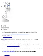
When you install a drive, you connect two cables—a DC power cable and an interface cable—to the back of the drive.
Power Cable Connector
1
power cable
2
power input connector
Drive Interface Connector
1
interface connector
2
colored stripe on cable
3
interface cable
Most interface connectors are keyed for correct insertion; that is, a notch or a missing pin on one connector matches a tab or
a filled-in hole on the other connector. Keyed connectors ensure that the pin-1 wire in the cable (indicated by the colored
stripe along one edge of the cable) goes to the pin-1 end of the connector. The pin-1 end of a connector on a board or a card
is usually indicated by a silk-screened "1" printed directly on the board or card.
NOTICE:
When you connect an interface cable, do not place the colored stripe away from pin 1 of the connector.
Reversing the cable prevents the drive from operating and could damage the controller, the drive, or both.
Summary of Contents for GX260 - Optiplex Pentium 4 2.0GHz 512MB 40GB CD
Page 6: ......
Page 29: ......
Page 37: ...Back to Contents Page ...
Page 40: ...information on resetting the chassis intrusion detector Back to Contents Page ...
Page 73: ......
Page 76: ......
Page 86: ...2 padlock ring 3 two release buttons one on each side Back to Contents Page ...
Page 111: ......
Page 128: ...1 release buttons 2 security cable slot 3 padlock ring Back to Contents Page ...
Page 155: ...Back to Contents Page ...
Page 186: ...Back to Contents Page ...
Page 210: ...Back to Contents Page ...
Page 232: ...BSMI Notice Taiwan Only ...


