48
System Board
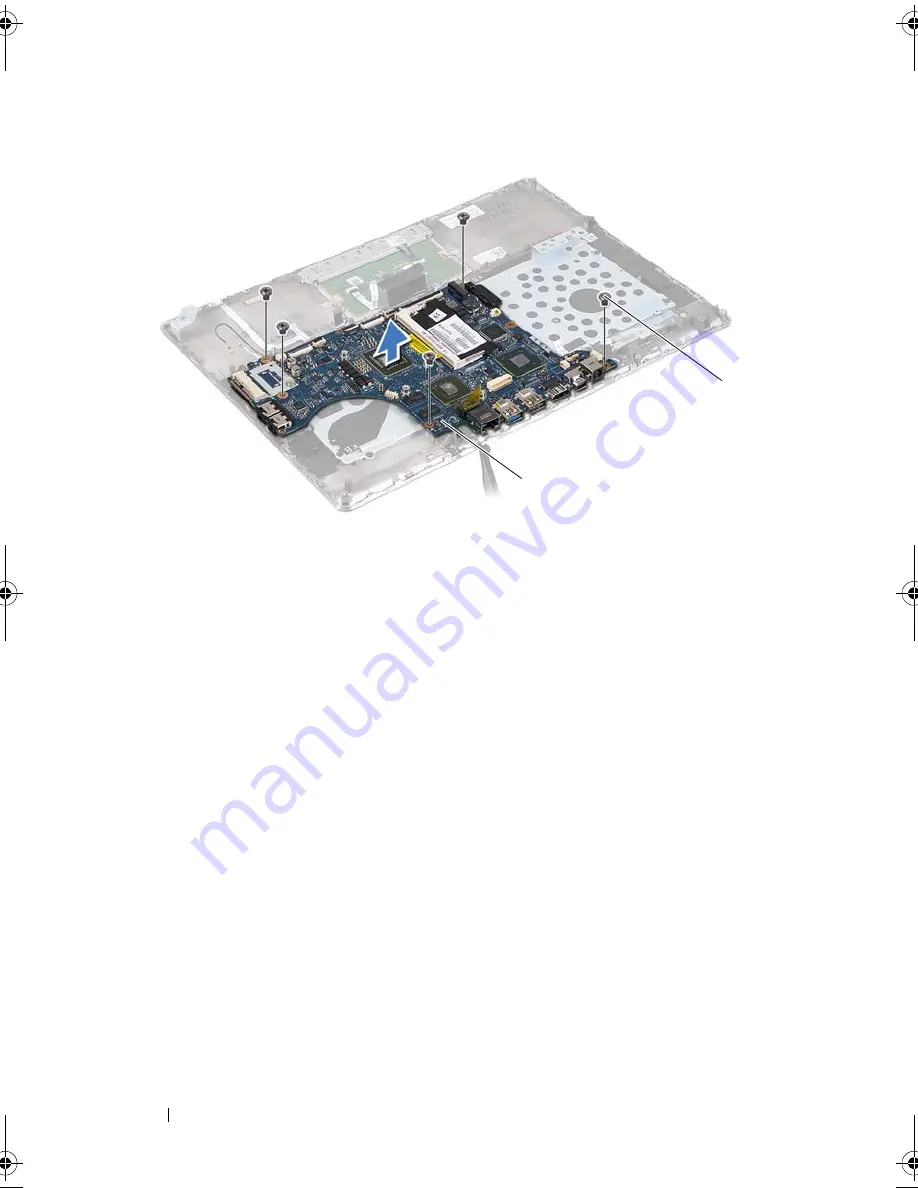
Replacing the System Board
1
Follow the instructions in "Before You Begin" on page 7.
2
Replace the memory module(s) (see "Replacing the Memory Module(s)"
on page 18).
3
Place the system board on the palm-rest assembly.
4
Replace the five screws that secure the system board to the palm-rest
assembly.
5
Slide the power-button board cable into the system-board connector and
press down on the connector latch to secure the cable.
6
Connect the display cable, ambient-light-sensor cable, and display-
converter board cable to the system-board connectors.
7
Adhere the tape over the network connector on the system board.
8
Connect the speaker cable to the system-board connector.
9
Slide the keyboard cable, touch-pad cable, keyboard-backlight cable, and
hall-sensor cable into the system board connectors and press down on the
connector latch to secure the cable.
1
system board
2
screws (5)
1
2
book.book Page 48 Thursday, May 3, 2012 3:09 PM
Summary of Contents for I14Z-2026DBK
Page 10: ...10 Before You Begin ...
Page 13: ...Base Cover 13 ...
Page 14: ...14 Base Cover ...
Page 34: ...34 Optical Drive ...
Page 38: ...38 Hall Sensor Board ...
Page 44: ...44 Heat Sink and Fan ...
Page 50: ...50 System Board ...
Page 56: ...56 Keyboard 6 Lift the keyboard bracket off the palm rest assembly 1 antenna cables 2 1 ...
Page 60: ...60 Keyboard ...


