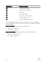
Light Pattern
Problem description
2,5
Invalid memory installed
2,6
System board or chipset error
2,7
LCD failure
3,1
CMOS battery failure
3,2
PCI or video card or chip failure
3,3
Recovery image not found
3,4
Recovery image found but invalid
The computer may emit a series of beeps during start-up if the errors or problems
cannot be displayed. The repetitive beep codes help the user troubleshoot problems
with the computer.
Camera status light:
Indicates whether the camera is in use.
•
Solid white – Camera is in use.
•
Off – Camera is not in use.
Caps Lock status light:
Indicates whether Caps Lock is enabled or disabled.
•
Solid white – Caps Lock enabled.
•
Off – Caps Lock disabled.
112
Summary of Contents for Inspiron 15 3000 Series
Page 24: ...6 Lift the keyboard off the palm rest assembly 24 ...
Page 28: ...6 Remove the two screws M2x5 that secure the base cover to the palm rest assembly 28 ...
Page 30: ...9 Remove the optical drive interposer 30 ...
Page 35: ...35 ...
Page 39: ...6 Lift the hard drive off the hard drive bracket 39 ...
Page 42: ...2 Slide and remove the memory module from the memory module slot 42 ...
Page 46: ...4 Slide and remove the wireless card from the wireless card slot 46 ...
Page 52: ...7 Note the power button board cable routing and peel it off the palm rest assembly 52 ...
Page 54: ...4 Replace the battery 54 ...
Page 59: ...4 Lift the I O board off the palm rest assembly 59 ...
Page 62: ...62 ...
Page 65: ...2 Lift the heat sink off the system board Integrated Eight screws Discrete Four screws 65 ...
Page 68: ...3 Lift the fan off the palm rest assembly 68 ...
Page 71: ...71 ...
Page 77: ...14 Lift the system board off the palm rest assembly 77 ...
Page 81: ...3 Lift the touch pad bracket off the palm rest assembly 81 ...
Page 82: ...4 Lift the touch pad off the palm rest assembly 82 ...
Page 85: ...3 Lift the power adapter port off the palm rest assembly 85 ...
Page 90: ...7 Open the palm rest assembly at an angle and slide it off the display assembly 90 ...
Page 97: ...5 Lift the display panel off the display back cover and antenna assembly 97 ...
Page 100: ...3 Lift the camera off the display back cover and antenna assembly 100 ...
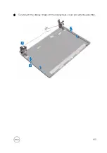
Page 103: ...2 Carefully lift the display hinges off the display back cover and antenna assembly 103 ...
Page 106: ...106 ...
Page 109: ...109 ...

