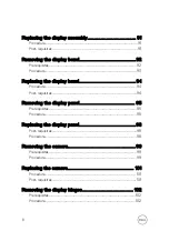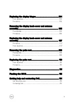
Replacing the status-light lens.....................................72
........................................................................................ 72
............................................................................................... 72
Removing the system board.........................................73
........................................................................................... 73
............................................................................................... 74
Replacing the system board.........................................78
............................................................................................... 78
........................................................................................ 79
Removing the touch pad..............................................80
........................................................................................... 80
............................................................................................... 80
Replacing the touch pad.............................................. 83
............................................................................................... 83
........................................................................................83
Removing the power-adapter port...............................84
........................................................................................... 84
............................................................................................... 84
Replacing the power-adapter port............................... 86
............................................................................................... 86
........................................................................................86
Removing the display assembly....................................87
........................................................................................... 87
............................................................................................... 87
7
Summary of Contents for Inspiron 15 3000 Series
Page 24: ...6 Lift the keyboard off the palm rest assembly 24 ...
Page 28: ...6 Remove the two screws M2x5 that secure the base cover to the palm rest assembly 28 ...
Page 30: ...9 Remove the optical drive interposer 30 ...
Page 35: ...35 ...
Page 39: ...6 Lift the hard drive off the hard drive bracket 39 ...
Page 42: ...2 Slide and remove the memory module from the memory module slot 42 ...
Page 46: ...4 Slide and remove the wireless card from the wireless card slot 46 ...
Page 52: ...7 Note the power button board cable routing and peel it off the palm rest assembly 52 ...
Page 54: ...4 Replace the battery 54 ...
Page 59: ...4 Lift the I O board off the palm rest assembly 59 ...
Page 62: ...62 ...
Page 65: ...2 Lift the heat sink off the system board Integrated Eight screws Discrete Four screws 65 ...
Page 68: ...3 Lift the fan off the palm rest assembly 68 ...
Page 71: ...71 ...
Page 77: ...14 Lift the system board off the palm rest assembly 77 ...
Page 81: ...3 Lift the touch pad bracket off the palm rest assembly 81 ...
Page 82: ...4 Lift the touch pad off the palm rest assembly 82 ...
Page 85: ...3 Lift the power adapter port off the palm rest assembly 85 ...
Page 90: ...7 Open the palm rest assembly at an angle and slide it off the display assembly 90 ...
Page 97: ...5 Lift the display panel off the display back cover and antenna assembly 97 ...
Page 100: ...3 Lift the camera off the display back cover and antenna assembly 100 ...
Page 103: ...2 Carefully lift the display hinges off the display back cover and antenna assembly 103 ...
Page 106: ...106 ...
Page 109: ...109 ...


