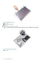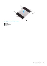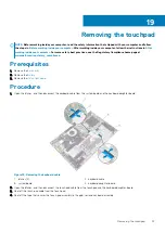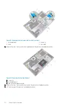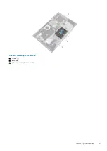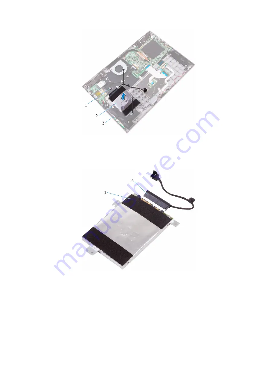
Figure 9. Removing the hard-drive assembly
a. screws (3)
b. hard-drive assembly
c. palm rest and keyboard assembly
6. Disconnect the interposer from the hard-drive assembly.
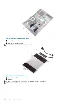
Figure 10. Disconnecting the interposer
a. hard-drive assembly
b. interposer
7. Remove the four screws (M3x3) that secure the hard-drive bracket to the hard drive.
8. Lift the hard drive off the hard-drive bracket.
20
Removing the hard drive
Summary of Contents for Inspiron 15-5568
Page 1: ...Inspiron 15 5568 2 in 1 Service Manual Regulatory Model P58F Regulatory Type P58F001 ...
Page 27: ...7 wireless card bracket Post requisites Replace the base cover Replacing the wireless card 27 ...
Page 70: ...3 display cable 4 display panel assembly 70 Removing the camera ...
Page 73: ...5 sensor board 6 display panel assembly Removing the sensor board 73 ...

