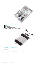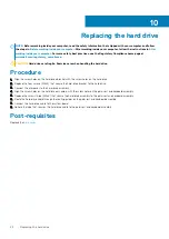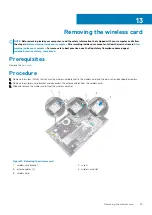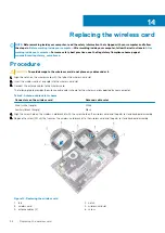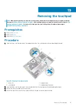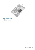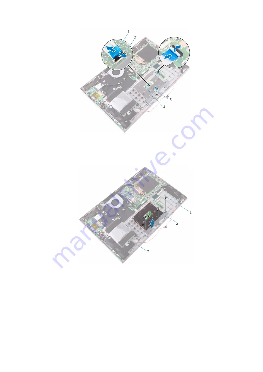
Figure 19. Removing the touch-pad cable from the touch pad
1. touch-pad cable
2. latches (2)
3. tape
4. touch pad
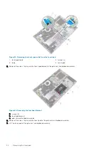
5. Remove the screws that secure the touch-pad bracket to the palm rest and keyboard assembly.
Figure 20. Removing the touchpad bracket
a. screws (3)
b. touch-pad bracket
c. palm rest and keyboard assembly
6. Remove the screws that secure the touch pad to the palm rest and keyboard assembly.
7. Lift the touch pad off the palm rest and keyboard assembly.
34
Removing the touchpad
Summary of Contents for Inspiron 15-5568
Page 1: ...Inspiron 15 5568 2 in 1 Service Manual Regulatory Model P58F Regulatory Type P58F001 ...
Page 27: ...7 wireless card bracket Post requisites Replace the base cover Replacing the wireless card 27 ...
Page 70: ...3 display cable 4 display panel assembly 70 Removing the camera ...
Page 73: ...5 sensor board 6 display panel assembly Removing the sensor board 73 ...

