background image

A-2

Dell Inspiron 2000 System Reference and Troubleshooting Guide

"

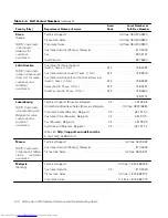
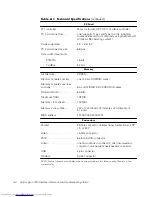
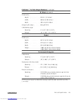
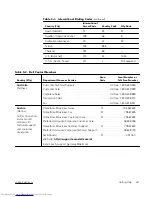
PCI controller. . . . . . . . . . . . . . .  Texas Instruments PCI 1211 CardBus controller

PC Card connectors  . . . . . . . . . one (supports Type I and Type II cards, including 

zoomed video cards on computers using the Microsoft 
Windows 98 operating system)

Cards supported . . . . . . . . . . . . 3.3 V and 5 V

PC Card connector size . . . . . . . 68 pins

Data width (maximum)

PCMCIA . . . . . . . . . . . . . . .  16 bits

CardBus . . . . . . . . . . . . . . .  32 bits

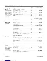
Architecture. . . . . . . . . . . . . . . .  SDRAM

Memory module sockets  . . . . . one 144-pin SODIMM socket

Memory module capacities
and type  . . . . . . . . . . . . . . . . . .  64- and 128-MB 3.3-V SDRAM modules

Minimum RAM . . . . . . . . . . . . .  64-MB

Maximum RAM. . . . . . . . . . . . . 128 MB

Memory clock speed. . . . . . . . . 100 MHz

Memory  access  time   .  .  .  .  .  .  .  .  CL2 or CL3 (Note: CL3 indicates a CAS latency of              

3 clocks)

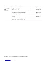
BIOS address  . . . . . . . . . . . . . .  FF000:0000-F000:FFFF

Parallel. . . . . . . . . . . . . . . . . . . .  25-hole connector; unidirectional, bidirectional, EPP 

1.9, or ECP

Video . . . . . . . . . . . . . . . . . . . . .  15-hole connector

PS/2. . . . . . . . . . . . . . . . . . . . . .  6-pin mini-DIN connector

Audio . . . . . . . . . . . . . . . . . . . . .  one microphone-in connector; one line-in/audio-in   

connector; one headphones/speakers connector

USB . . . . . . . . . . . . . . . . . . . . . .  4-pin connector

Modem

RJ-45 connector

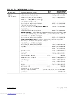
"$%# "%!'


NOTE: For the full name of an abbreviation or acronym used in this table, see the Glossary in the       
system Help.

Summary of Contents for Inspiron 2000

Page 1: ... ...

Page 2: ...indows NT are registered trademarks of Microsoft Corporation Intel is a registered trademark of Intel Corporation 3Com is a registered trademark of 3Com Corporation As an ENERGY STAR Partner Dell Computer Corporation has determined that this product meets the ENERGY STAR guidelines for ENERGY STAR efficiency Other trademarks and trade names may be used in this document to refer to either the entit...

Page 3: ...ers or other items that will reduce cooling also do not use the AC adapter inside a carrying case Do not use your computer in a wet environment for example near a bathtub sink or swimming pool or in a wet basement Do not push objects into air vents or openings of your computer Doing so can cause fire or electric shock by shorting out interior components Use only the AC adapter and batteries that a...

Page 4: ...ontinuous operation Do not dispose of battery packs in a fire They may explode Check with local authorities for disposal instructions When traveling do not check the computer as baggage You can put your computer through an X ray security machine but never put your computer through a metal detector If you have the computer checked by hand be sure to have a charged battery available in case you are ...

Page 5: ... dampened with water rather than with liquid or aerosol cleaners Clean the display with a soft clean cloth and commercial window cleaner that does not contain wax or abrasives Apply the cleaner to the cloth then stroke the cloth across the display in one direction moving from the top of the display to the bottom If the display contains grease or some other contaminant use isopropyl alcohol instead...

Page 6: ...e sitting in front of the monitor Use a chair that provides good lower back support Keep your forearms horizontal with your wrists in a neutral comfortable position while using the keyboard trackball touch pad or external mouse Always use the palmrest with the keyboard touch pad or trackball Leave space to rest your hands when using an external mouse Let your upper arms hang naturally at your side...

Page 7: ...lso take the following steps to prevent damage from electrostatic discharge ESD When unpacking a static sensitive component from its shipping carton do not remove the component from the antistatic packing material until you are ready to install the component Just before unwrapping the antistatic packaging be sure to discharge static electricity from your body When transporting a sensitive componen...

Page 8: ...x ...

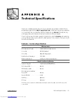
Page 9: ...oftware Solutions provides detailed instructions for reinstalling system drivers and software Chapter 5 Getting Help describes the help tools Dell provides to assist you if you have a problem with the computer It also explains how and when to call Dell for technical assistance Appendix A Technical Specifications is intended primarily as reference material if you are interested in learning more abo...

Page 10: ...t to Programs Dell Documents and click Dell Inspiron 2000 System Help You may also have one or more of the following documents Information updates describing changes to your computer or software NOTE Always read any included update before consulting any other documentation because the updates contain the latest information Operating system documentation is included if Dell installed the operating ...

Page 11: ...purposes only and are not intended to be typed at that particular point in the discussion Example Use the setup command to In contrast commands presented in the Courier New font are intended to be typed as part of an instruction Example Type to format the diskette in drive A Filenames and directory names are presented in lowercase bold Examples autoexec bat and c windows Syntax lines consist of a ...

Page 12: ...be text that you are instructed to type as part of a command referred to as a command line Screen text is presented in the Courier New font Example The following message appears on your screen Variables are symbols for which you substitute a value They are presented in italics Example module n where n represents the memory module number ...

Page 13: ...Battery 2 2 Battery Charge Gauge 2 3 Percentage of Charge 2 4 External Media Bay Cable 2 5 Using the External Media Bay 2 5 Device Configuration 2 7 Installing Devices With Softex BayManager Software 2 7 Using the Diskette Drive Module as an External Device 2 8 Installing an Internal Hard Disk Drive 2 8 Returning a Hard Disk Drive to Dell 2 11 Connecting Other External Devices 2 11 Checking the Ba...

Page 14: ...uter is Dropped or Damaged 3 12 Running the Dell Diagnostics 3 12 Starting the Dell Diagnostics 3 13 Dell Diagnostics Main Screen 3 15 Confirming the System Configuration Information 3 16 Using the Dell Diagnostics 3 17 Menu 3 17 Keys 3 17 Device Group 3 17 Device 3 17 Test 3 18 Versions 3 18 Partitioning and Formatting the Hard Disk Drive 4 1 Installing the Windows 98 Operating System 4 3 Install...

Page 15: ...ontact Numbers 5 7 Accessing the System Setup Program B 2 Main Menu B 2 Advanced Menu B 4 I O Device Configuration Submenu B 6 Security Menu B 8 Power Menu B 10 Boot Menu B 13 Exit Menu B 15 System Messages C 1 0 FCC Notices U S Only D 2 Class A D 3 Class B D 3 Modem Regulatory Information D 3 Fax Branding D 4 IC Notice Canada Only D 4 Modem Regulatory Information D 5 CE Notice European Union D 6 ...

Page 16: ...ware Products E 6 Previous Products E 7 Software E 7 Additional Information E 7 5 Figure 1 1 Front View of the Computer 1 3 Figure 1 2 Back View of the Computer 1 4 Figure 1 3 Bottom View of the Computer 1 5 Figure 1 4 ENERGY STAR Emblem 1 6 Figure 2 1 Using the AC Adapter 2 2 Figure 2 2 Removing a Battery 2 3 Figure 2 3 Battery Charge Gauge 2 4 Figure 2 4 External Media Bay Cable 2 5 Figure 2 5 C...

Page 17: ...C Class B Regulatory Mark D 9 Table 3 1 Boot Routine Indications 3 5 Table 3 2 IRQ Line Assignments 3 9 Table 5 1 International Dialing Codes 5 8 Table 5 2 Dell Contact Numbers 5 9 Table A 1 Technical Specifications A 1 Table B 1 Main Menu Options B 3 Table B 2 Advanced Menu Options B 4 Table B 3 I O Device Configuration Submenu Options B 6 Table B 4 Security Menu Options B 8 Table B 5 Power Menu ...

Page 18: ...xx ...

Page 19: ...te drive and installing a different device in the bay see Using the External Media Bay in Chapter 2 Because the Microsoft Windows NT operating system does not support DVD technology the DVD ROM drive is available only on computers that use the Windows 98 Second Edition operating system A 256 bit hardware accelerated NeoMagic NM2200 accelerated graphics port AGP video controller with 2 5 MB of vide...

Page 20: ...m ion battery in the battery bay 0 A PC Card slot with one connector for a 3 3 or 5 volt V PC Card The PC Card connector supports zoomed video ZV port cards NOTES The PC Card controller supports the CardBus standard for 32 bit data transfer on the PC Card Windows NT does not support zoomed video One high performance serial port connector One parallel port connector that can be set to unidirectiona...

Page 21: ...riable speed fan and microprocessor speed changes to keep the computer running at the optimum temperature 5 6 PC Card slot display latch power button security cable slot keyboard device access status indicators keyboard status indicators touch pad touch pad buttons display hard disk drive ...

Page 22: ...ooting Guide 7 6 modem connector video connector parallel port connector external media bay cable connector USB connector PS 2 connector fan intake exhaust vents external media bay speaker jack microphone jack AC adapter connector air inlet NIC connector ...

Page 23: ... how to communicate with various types of hard ware devices such as CD ROM drives or speakers If you need to reinstall these drivers or if you installed your own operating system use the System Software CD that accompanied your computer Instructions for installing the drivers are provided in Chapter 4 System Software Solutions NOTE The drivers on the System Software CD are the ones Dell installed ...

Page 24: ...3 Certain configurations of Dell computer systems comply with the requirements set forth by the Environmental Protection Agency EPA for energy efficient computers If the front panel of your computer bears the ENERGY STAR Emblem see Figure 1 4 your original configuration complies with these requirements and all ENERGY STAR power management features of the computer are enabled NOTES As an ENERGY STA...

Page 25: ...eekends Dell offers the following upgrade options Additional batteries External pointing devices keyboards and a numeric keypad External monitors External speakers headphones and microphones Printers Hard disk drives DVD ROM drives SuperDisk LS 120 drives AC adapter PC Cards Carrying case To order any of these options or upgrades call Dell For instructions see Chapter 5 Getting Help or the Contact...

Page 26: ...1 8 Dell Inspiron 2000 System Reference and Troubleshooting Guide ...

Page 27: ...le and an AC power cable see Figure 2 1 You can connect the AC adapter with your computer either turned on or off The AC adapter works with electrical outlets worldwide However power connectors vary among countries Before you use AC power in a foreign country you may need to obtain a new power cable designed for use in that country NOTE If you are running your computer on AC power with a battery i...

Page 28: ...Plug the AC adapter cable into the AC adapter connector on the computer Your computer comes with a lithium ion battery installed in the battery bay The battery provides power to your computer when AC power is not available 1222 To install a battery in the battery bay perform the following steps 1 Save and close any open files exit any open application programs and shut down the computer AC power c...

Page 29: ...y fit into four slots in the side wall of the computer 4 Press the battery firmly into place flush with the surrounding surface Make sure that the battery latch is completely closed before turning the com puter right side up The battery charge gauge located on the battery and accessible on the underside of the computer consists of four indicators and a test button Each indicator represents 25 perc...

Page 30: ...d allow the battery to charge overnight and check it the next day If the battery is fully discharged it takes a much longer time than usual to recharge it To purchase a new battery call Dell or access the Dell World Wide Web site at http www dell com Dispose of the old battery properly See Battery Disposal in Appendix D The battery charge gauge uses its four indicator lights to show the percent of...

Page 31: ...re fully engaged and the con nector is fully seated To remove the cable from a device press in on the securing clips while pulling the connector straight out The media bay supports the following devices Diskette drive CD ROM drive DVD ROM NOTE Because the Microsoft Windows NT operating system does not support DVD technology the DVD ROM drive is available only on computers that use the Microsoft Wi...

Page 32: ...r and click Insert Bay Devices If your computer is not running Softex BayManager Save your work close all open files and application programs and turn off the computer 3 2 If the external media bay contains a device see Figure 2 5 remove the media bay cable from the back of the bay by pressing in on the securing clips while pull ing the connector straight out Then remove the device by sliding the ...

Page 33: ...omputer in step 1 Press the power button to turn the com puter back on Some devices require that you configure them before using them for the first time For more information see the documentation that came with the device 2 Your computer may be using Softex BayManager software This software allows you to change devices in the external media bay while the computer is running You do not have to shut...

Page 34: ... as illustrated Read the following notices carefully before attempting to replace your hard disk drive NOTES You will need the Microsoft Windows installation CD and the System Soft ware CD to install software on the new hard disk drive The computer s basic input output system BIOS may not support hard disk drives obtained from vendors other than Dell Dell does not guarantee compatibility or provid...

Page 35: ... then remove the battery 3 Remove the old hard disk drive carrier assembly from the drive bay Using a 0 very small Phillips head screwdriver remove the two screws that secure the drive carrier assembly see Figure 2 7 Save the screws for use later in this procedure With the computer still upside down press down on the drive carrier assembly s three grip lines and pull the assembly straight out to t...

Page 36: ...el facing down toward the top of the computer Push the assembly straight in until it snaps into place with the assembly flush with the computer case 6 Replace the screws you removed in step 3 7 Turn on the computer 8 Partition and format the drive as described in Partitioning and Formatting the Hard Disk Drive in Chapter 4 9 Install the operating system on the drive For instructions see Chapter 4 ...

Page 37: ...e 2 8 Otherwise the hard disk drive may be damaged while in transit 3 2 You can connect a variety of external devices to your computer For instructions refer to the section titled Connecting External Devices in the system Help To open the Help click the Start button point to Programs Dell Documents and click Dell Inspiron 2000 System Help hard disk drive ...

Page 38: ...2 12 Dell Inspiron 2000 System Reference and Troubleshooting Guide ...
Page 39: ... if possible If the problem is resolved check any documentation that came with the option you attempted to install or that describes the change you made In particular read any text files such as readme txt included with the software package or hardware product such files contain information that updates or supplements the documentation for the software or hardware Typically readme files provide in...

Page 40: ...roblem persists refer to Chapter 5 Getting Help for instructions on obtaining technical assistance 7 Loose or improperly connected cables are likely sources of problems for your computer external monitor or other peripherals such as a printer external keyboard or mouse A quick check of all cable connections can easily solve these problems If the connector has two small screws make sure the screws ...

Page 41: ...ion Electrical extension cords and keyboard and mouse extension cables Too many devices on a power strip or multiple power strips from one electrical outlet Electrical conduits in an adjoining wall or elevators on the other side of the wall Large metal beams inside the wall behind the computer If removing potential sources of problems does not help try moving the computer If you are experiencing p...

Page 42: ...it Try a different diskette in the drive If the new diskette works the original one may be defective Check drive operations at the MS DOS prompt in the Dell Diagnostics refer to Running the Dell Diagnostics found later in this chapter and the Windows operating system Check the settings on the Page One submenu of the system setup program as described in Appendix B Using the System Setup Program Run...

Page 43: ...ound later in this chapter Check the settings on the IDE Configuration submenu of the system setup program as described in Appendix B Using the System Setup Program You can clean a diskette drive using a commercially available cleaning kit These kits contain pretreated diskettes to nonabrasively remove contaminants that accumulate during normal operation If the kit does not contain instructions in...

Page 44: ...the diskette drive You can test this indicator by inserting a diskette into the drive typing at an MS DOS prompt and pressing Enter If the diskette drive access indicator does not light up see Drives found earlier in this chapter The CD ROM hard disk drive access indicator The CD ROM hard disk drive access indicator lights up when data is accessed on the CD ROM drive or the hard disk drive You can...

Page 45: ... software before installing it on the computer s hard disk drive Viruses can quickly use all available system memory damage and or destroy data stored on the hard disk drive and permanently affect the performance of the programs they infect Several commercial virus scanning programs are available for purchase and most bulletin board services BBSs archive freely distributed virus scanning programs ...

Page 46: ...the documentation that came with the application program to make sure the values or characters you are entering do not conflict with the application program you are using Make sure the operating system is compatible with the programs you use Keep in mind that whenever you change the parameters of the computer s operating system you may affect the successful operation of the programs Sometimes afte...

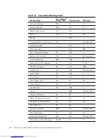
Page 47: ...n for the default IRQ line setting for each installed device Then consult Table 3 2 to configure the device for one of the available IRQ lines NOTES Installed devices cannot share the same COM port address The default address of the computer s serial port is COM1 To view IRQ line assignments in the Microsoft Windows 98 operating system click the Start button point to Settings and click Control Pan...

Page 48: ... conflicts before checking specific devices 6 Double click the malfunctioning device type in the Device Manager list 7 Double click the icon for the specific device in the expanded list The Properties window appears 8 If there is an IRQ conflict the Device status area in the Properties window reports what expansion cards or devices are sharing the device s IRQ Resolve the IRQ conflicts IRQ9 SCI in...

Page 49: ...eps 1 Turn off the computer and disconnect it from the AC adapter Then disconnect the AC adapter from the electrical outlet Turn off any attached peripherals and dis connect them from their power sources and then from the computer 2 Ground yourself by touching one of the metal connectors on the back of the computer 3 If the media bay is wet remove the device from the bay If the PC Card slot is wet...

Page 50: ...m the electrical outlet and then from the computer 3 Ground yourself by touching one of the metal connectors on the back of the computer 4 Remove the battery and the external media bay 5 Remove the hard disk drive For instructions refer to Installing an Internal Hard Disk Drive in Chapter 2 6 Reinstall the hard disk drive 7 Verify that any installed PC Card is properly seated in the PC Card connec...

Page 51: ...t describes the configuration of the devices in the selected device group Status messages that inform you whether device groups or subtests were completed successfully Error messages that appear if any problems are detected Whenever a major component or device in your computer does not function properly you may have a component failure As long as the microprocessor and the input and output compone...

Page 52: ...r display When you start the diagnostics the Dell logo screen appears followed by a message telling you that the diagnostics is loading After the diagnostics loads the Diagnostics Menu appears see Figure 3 1 The menu allows you to run all or specific diagnostic tests or to exit to the MS DOS prompt For a quick check of your computer select the Quickly Test All Devices option This option runs only ...

Page 53: ...of the screen the Device Groups area lists the diagnostic test groups in the order they will run if you select All from the Run tests menu category Press the up or down arrow key to highlight a test device group On the right side of the screen the Devices for Highlighted Group area lists the computer s currently detected hardware and some of the relevant settings Two lines at the bottom of the scr...

Page 54: ...tification tests of the microprocessor the video controller the keyboard con troller and other key components Basic input output system BIOS configuration information temporarily saved in RAM Do not be concerned if the Device Groups area does not list the names of all the components or devices you know are part of your computer For example you may not see a printer listed although you know one is ...

Page 55: ...criptions of the devices that you are testing The Help categories are explained in the following subsections The Menu Help category provides descriptions of the main menu screen area the Device Groups and the different diagnostic menus and commands and instructions on how to use them The Keys Help category explains the functions of the all of the keystrokes that can be used in Dell Diagnostics The...

Page 56: ...gory provides a thorough explanation of the test procedure of each presently highlighted test group subtest An example of the Diskette subtest Diskette Drive Seek Test is as follows The Versions Help category lists the version numbers of the subtests that are used by the Dell Diagnostics ...

Page 57: ... you must partition and format the drive Then you must assign logical drive letters to the partitions you created To partition and format the new hard disk drive and then assign logical drive letters to the partitions you created perform the following steps 6 1 Partition the hard disk drive using the partitioning software for your particular operating system When you set up the partition s on the ...

Page 58: ...out removing the CD ROM or DVD ROM drive from the external media bay connect the diskette drive to the computer as described in Using the Diskette Drive Module as an External Device in Chapter 2 4 Create the S2D partition For instructions see Save to Disk Suspend Utility found later in this chapter 5 Follow the instructions found later in this chapter to install the appropriate device drivers 6 In...

Page 59: ...abel a blank high density diskette as instructed insert the diskette into the diskette drive and then click OK 9 Follow the prompts on your screen to complete the installation All of your computer s drivers for Dell installed devices are operative when you receive the computer No further installation or configuration is needed However if you ever need to reinstall any of these drivers the driver f...

Page 60: ...l area net work LAN and MS DOS CD ROM drivers All Drivers and Applications includes the core drivers plus other applica tion programs such as the Yamaha Software Wavetable Softex BayManager your computer s system Help and various system utilities Custom lists all available drivers applications and utilities To perform a custom installation click Custom and then click the radio button for each item...

Page 61: ...n on or restart the computer 3 Press F2 as soon as you see the Dell logo screen to enter the system setup program If you wait too long and the operating system begins to load into memory let the computer complete the load operation Then shut down the computer and try again 4 Boot screen 5 Press F10 to save the settings and exit the system setup program The computer restarts and automatically begin...

Page 62: ...ur hard disk drive is unpartitioned and unformatted or you have a minimum of 150 MB of unpartitioned space on the drive For information on partitioning and formatting your drive see both your operating sys tem and your drive documentation To create the S2D file for computers running Microsoft Windows NT perform the fol lowing steps 1 Insert the Dell System Software CD into the CD ROM or DVD ROM dr...

Page 63: ...s Enter 1 0 To restore the default boot sequence perform the following steps 1 Turn on or restart the computer 2 Press F2 as soon as you see the Dell logo screen to enter the system setup program If you wait too long and the operating system begins to load into memory let the computer complete the load operation Then shut down the computer and try again 3 Enter the Boot screen and press F9 to rest...

Page 64: ...4 8 Dell Inspiron 2000 System Reference and Troubleshooting Guide ...
Page 65: ...r help with installation and troubleshooting procedures For more information refer to World Wide Web on the Internet found later in this chapter 5 If the preceding steps have not resolved the problem and you need to talk to a Dell technician call Dell s technical support service When prompted by Dell s automated telephone system enter your Express Service Code to route the call directly to the pro...

Page 66: ...er your system information to access help tools and information such as Support Y our Dell From this page you can access a number of tools and infor mation such as system documentation drivers and BIOS updates and self diagnostic tools for resolving many computer related issues by following interac tive flowcharts Ask Dudley Enter a question about your computer or about software This tool searches...

Page 67: ...ended it The AutoTech service is available 24 hours a day seven days a week You can also access this service through the technical support service For the telephone number to call refer to Dell Contact Numbers found later in this chapter 5 Dell takes full advantage of fax technology to serve you better Twenty four hours a day seven days a week you can call the Dell TechFax line toll free for all k...

Page 68: ...system to better understand your particular question Our technical support staff use computer based diagnostics to provide fast accurate answers to questions To contact Dell s technical support service first refer to the section titled Before You Call and then call the number for your country as listed in Dell Contact Numbers found later in this chapter If you have a problem with your order such a...

Page 69: ...ent packing materials You are responsible for paying shipping expenses You are also responsible for insuring any product returned and you assume the risk of loss during shipment to Dell Computer Corporation Collect on delivery C O D packages are not accepted Returns that are missing any of the preceding requirements will be refused at our receiving dock and returned to you NOTE Have your Express S...

Page 70: ...__________________________________________ _______________________________________________________________________________________________ Are you connected to a network yes no Network version and network card _______________________________________________________________ Programs and versions ___________________________________________________________________________ ____________________________...

Page 71: ...nd then the local number as shown in the following illustration To place a long distance call within your own country use area codes instead of international access codes country codes and city codes For example to call Paris France from Montpellier France dial the area code plus the local number as shown in the following illustration The codes required depend on where you are calling from as well...

Page 72: ... 45 Not required Finland Helsinki 990 358 9 France Paris Montpellier 00 33 1 4 Germany Langen 00 49 6103 Hong Kong 001 852 Not required Ireland Bray 16 353 1 Italy Milan 00 39 2 Japan Kawasaki 001 81 44 Korea Seoul 001 82 2 Luxembourg 00 352 Macau 853 Not required Malaysia Penang 00 60 4 Mexico Colonia Granada 95 52 5 Netherlands Amsterdam 00 31 20 New Zealand 00 64 Norway Lysaker 095 47 Not requi...

Page 73: ...5 Transaction Sales toll free 1 800 808 312 Fax toll free 1 800 818 341 Austria Vienna NOTE Customers in Austria call Germany for technical support and customer assistance Home Small Business Sales 01 795 567602 Home Small Business Fax 01 795 67605 Home Small Business Customer Care 01 795 67603 Preferred Accounts Corporate Customer Care 0660 8056 Home Small Business Technical Support 01 795 67604 ...

Page 74: ... Malaysia 810 4949 Transaction Sales Penang Malaysia 810 4955 Canada North York Ontario NOTE Customers in Canada call the U S A for access to TechConnect BBS Automated Order Status System toll free 1 800 433 9014 AutoTech Automated technical support toll free 1 800 247 9362 Customer Care From outside Toronto toll free 1 800 387 5759 Customer Care From within Toronto 416 758 2400 Customer Technical...

Page 75: ...witchboard 02 22 83 27 11 Web site http support euro dell com cz E mail czech_dell dell com Denmark Horsholm NOTE Customers in Denmark call Sweden for fax technical support Technical Support 45170182 Customer Care 45170181 Switchboard 45170100 Fax Technical Support Upplands Vasby Sweden 859005594 Fax Switchboard 45170117 Web site http support euro dell com dk E mail den_support dell com Finland He...

Page 76: ...b_fr_tech dell com Germany Langen Technical Support 06103 971 200 Technical Support Fax 06103 971 222 Home Small Business Customer Care 06103 971 530 Preferred Accounts Customer Care 06103 971 420 TechConnect BBS 06103 971 666 Switchboard 06103 971 0 Corporate Customer Care 06103 971 560 Web site http www dell de support E mail tech_support_germany dell com Hong Kong NOTE Customers in Hong Kong ca...

Page 77: ...chboard 01 286 0500 Web site http support euro dell com ie E mail dell_direct_support dell com Italy Milan Technical Support 2 57782 690 Customer Care 2 57782 555 Sales 2 57782 411 Fax 2 57503530 Switchboard 2 57782 1 Web site http support euro dell com it E mail support_italy dell com Japan Kawasaki Technical Support toll free 0088 22 7890 Technical Support Inspiron toll free 0120 1982 56 Y2K Sup...

Page 78: ...512 728 4397 SalesFax Austin Texas U S A 512 728 4600 728 3772 Luxembourg NOTE Customers in Luxembourg call Belgium for sales customer and technical assistance Technical Support Brussels Belgium 02 481 92 88 Home Small Business Sales Brussels Belgium toll free 080016884 Corporate Sales Brussels Belgium 02 481 91 00 Customer Care Brussels Belgium 02 481 9119 Fax Brussels Belgium 02 481 92 99 Switch...

Page 79: ...usiness Sales toll free 0800 0663 Home Small Business Sales Fax 020 682 7171 Corporate Sales 020 581 8818 Corporate Sales Fax 020 686 8003 Fax 020 686 8003 Switchboard 020 581 8818 Web site http support euro dell com nl E mail tech_nl dell com New Zealand Technical Support Dell Dimension systems only 2 50 GST per call 0900 51010 Technical Support Other systems 0800 446 255 Customer Service 0800 44...

Page 80: ...vice Penang Malaysia 04 810 4949 Transaction Sales toll free 800 6011 054 Corporate Sales toll free 800 6011 053 South Africa Johannesburg Technical Support 011 709 7710 Customer Care 011 709 7710 Sales 011 706 7700 Fax 011 709 0495 Switchboard 011 709 7700 Web site http support euro dell com za E mail dell_za_support dell com Southeast Asian Pacific Countries excluding Australia Brunei China Hong...

Page 81: ...ttp support euro dell com se E mail swe_support dell com Switzerland Geneva Technical Support 0844 811 411 Customer Care 0848 802 802 Fax 022 799 01 90 Switchboard 022 799 01 01 Web site http support euro dell com ch E mail swisstech dell com Taiwan NOTE Customers in Taiwan call Malay siafor customer assistance Technical Support toll free 0080 651 226 0800 33 557 Customer Service Penang Malaysia 8...

Page 82: ...Bracknell Technical Support 0870 908 0800 Corporate Customer Care 01344 720206 Home Small Business Customer Care 0870 906 0010 TechConnect BBS 0870 908 0610 Sales 01344 720000 AutoFax 0870 908 0510 Web site http support euro dell com uk E mail dell_direct_support dell com ...

Page 83: ... VARs Customer Service and Technical Support Return Material Authorization Numbers toll free 1 800 822 8965 Public Americas International systems purchased by governmental agencies local state or federal or educational institutions Customer Service and Technical Support Return Material Authorization Numbers toll free 1 800 234 1490 Dell Sales toll free 1 800 289 3355 toll free 1 800 879 3355 Spare...

Page 84: ...5 20 Dell Inspiron 2000 System Reference and Troubleshooting Guide ...

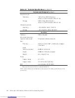
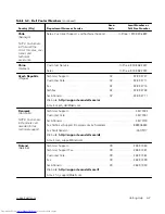
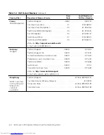
Page 85: ...by clicking Inspiron and selecting your system by name but you have to select options from a series of menus to reach the same information Microprocessor type Intel mobile microprocessor L1 cache 32 KB internal L2 cache 256 KB integrated External bus frequency 100 MHz Math coprocessor internal to the microprocessor System chip set Intel Mobile 443BX PIIX4m Data bus width 64 bits DRAM bus width 64 ...

Page 86: ...pin SODIMM socket Memory module capacities and type 64 and 128 MB 3 3 V SDRAM modules Minimum RAM 64 MB Maximum RAM 128 MB Memory clock speed 100 MHz Memory access time CL2 or CL3 Note CL3 indicates a CAS latency of 3 clocks BIOS address FF000 0000 F000 FFFF Parallel 25 hole connector unidirectional bidirectional EPP 1 9 or ECP Video 15 hole connector PS 2 6 pin mini DIN connector Audio one microp...

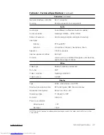
Page 87: ... speakers Internal speaker amplifier 500 mW Controls volume can be controlled through key combinations application program menus Video type 256 bit hardware accelerated Data bus AGP Video controller NeoMagic NM2200 Video memory 2 5 MB Type SVGA active matrix color TFT Maximum resolution colors 800 x 600 pixels 262 144 color display Response time typical 50 ms rise 20 ms fall Operating angle 0 clos...

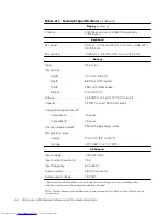
Page 88: ...WH for 4 cell 34 WH for 6 cell Charge time approximate 1 Computer on 1 5 hours Computer off 1 5 hours Life span approximate 1 350 discharge charge cycles Temperature range Charge 0 to 40 C 32 to 104 F Storage 20 to 60 C 4 to 140 F Input voltage 100 to 240 VAC Input current maximum 1 5 A Input frequency 50 to 60 Hz Output current 2 64 A maximum Rated output voltage 19 0 VDC 1 Battery performance fe...

Page 89: ...ight 1 665 kg 3 67 lb with 6 cell battery 1 618 kg 3 57 lb with 4 cell battery Temperature Operating 0 to 40 C 32 to 104 F Storage 20 to 65 C 4 to 149 F Relative humidity maximum Operating 10 to 90 noncondensing Storage 5 to 95 noncondensing Maximum vibration Operating 0 9 GRMS using a random vibration spectrum that simulates user environment Storage 1 3 GRMS using a random vibration spectrum that...

Page 90: ...nterface PS 2 compatible X Y position resolution graphics table mode 20 points mm 500 points inch Size Thickness 0 69 0 15 mm 0 027 0 006 inch at highest component Width sensor active area 64 88 mm 2 55 inch Height 48 88 mm 1 54 inch rectangle Weight 6 0 0 5g 0 21 oz Power Supply voltage 5 V 10 Supply current 4 0 mA nominal operating ESD In accordance with IEC 801 2 1 Measured with the hard disk d...

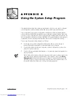
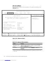
Page 91: ... the incorrect configuration setting You can use the system setup program as follows To change your system configuration information after you add change or remove hardware connected to or installed inside your computer To verify information about your computer s current configuration such as the amount of system memory To set or change user selectable features for example power management or secu...

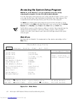
Page 92: ... how the computer is config ured In addition to the Main menu see Figure B 1 you can also access the System Devices menu Security menu Power menu Boot menu and Exit menu NOTE When you press F9 and press Enter to confirm the computer resets the default values for each option in that menu When you press F10 and press Enter to confirm the computer saves the current settings and exits the system setup...

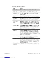
Page 93: ...Screen is Enabled the default a Phoe nix BIOS Setup Utility summary screen appears during system boot after the POST The summary screen lists many of the system setup settings When this option is set to Dis abled the summary screen does not appear Quiet Boot When set to Enabled default prevents the diagnostic POST messages and summary screen from appearing at system start up When set to Disabled a...

Page 94: ...enu 5 9 7 1 9 4 1 5 1 5 3 9 9A 4 5 6 8 94 1 8 7 9 8 B 1 1 4 7 7 4 9 7 1 6 I O Device Config uration Select this option and press Enter to display the I O Device Configuration submenu L2 Cache Sets the level 2 L2 cache to Enabled the default or Disabled NOTE For the full name of an abbreviation or acronym used in this table see the Glossary in the system Help ...

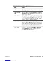
Page 95: ...on to Scroll Lock the default if you are using an external keyboard Set this option to Disabled to disable this function on the external keyboard Display Device Selection Specifies whether the screen image will appear on the com puter display an attached external monitor or both Options are LCD the display CRT an external monitor and LCD CRT If this option is set to CRT but no external monitor is ...

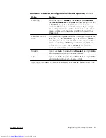
Page 96: ...C A2C 4 9 0 4 5 6 8 94 1 8 7 9 8 7 9 7 1 6 1 5 5 9 7 1 176 6 Serial port A Enabled sets the Serial port A Base I O Address to 3F8h IRQ4 If there is a conflict between two or more addresses an asterisk appears next to the port type Disabled disables the serial port to conserve power NOTE For the full name of an abbreviation or acronym used in this table see the Glossary in the system Help ...

Page 97: ...nfigures the integrated local bus IDE adapter Options are Both default Disabled Primary or Secondary If Both is selected you can access both the hard disk drive and the media bay device s If Primary is selected only the hard disk drive is accessible When Disabled the media bay device s and hard disk drive are disabled Modem Options are Auto the default and Disabled Setting to Auto automatically co...

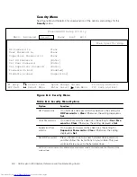
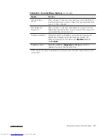
Page 98: ...ord is If no user password has been set the setting for User Pass word is is Clear Otherwise the setting displayed is Set Supervisor Pass word is If no supervisor password has been set the setting for Supervisor Password is is Clear Otherwise the setting displayed is Set Set HD Password Press Enter to set up a new hard disk drive password and then follow the instructions on your screen This pass w...

Page 99: ...en follow the instructions on your screen This password can replace the user password Password on Boot When this option is enabled you must enter a password before the computer loads the operating system into memory Settings for this option are Disabled default and Enabled Diskette access Specifies whether a Supervisor or User password is required to access the diskette drive 6 NOTE For the full n...

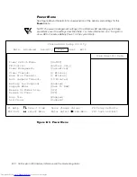
Page 100: ... the options and settings for the Power menu NOTE The power management settings of the Windows 98 operating system take precedence over the settings described here For more information see Using Win dows 98 to Conserve Battery Power in the system Help 8 4 5 577 9 5 1 9 D A A 5 A 1 577 A 5 577 9 4 5 6 7 8 94 1 8 7 9 8 ...

Page 101: ...t allows the greatest system performance and sets Video Timeout to 10 minutes Hard Disk Timeout to 5 minutes and Auto Suspend Timeout to 10 minutes Video Timeout Lets you determine how long the keyboard touch pad and PS 2 mouse remain idle no I O activity before the display and backlight turn off The display and backlight turn on again at the first attempt to access the keyboard touch pad PS 2 mou...

Page 102: ...er may take several seconds to return to normal operation When set to Save to Disk the computer copies all system data to a reserved area on the hard disk drive and then turns off all power to the computer When the computer resumes normal operation the same programs will be running and the same files will be open that were loaded before you acti vated this mode Use save to disk suspend mode to con...

Page 103: ...e to normal operation To use this option you must set Suspend Mode to Save to RAM Auto Dim Extends battery life by setting the computer to automatically decrease the brightness of the display when running on bat tery power Options are Enabled the default and Disabled Lid Close Specifies how the computer will respond when the display lid is closed When set to Active the default the computer switche...

Page 104: ... hard disk drive If it fails to boot from the hard disk drive the computer does not attempt to boot from the diskette drive ATAPI CD ROM Drive The computer attempts to boot first from a bootable CD If it does not detect a bootable CD in the CD ROM or DVD ROM drive the computer tries to boot from the next device on the list If a CD is in the CD ROM or DVD ROM drive but the CD does not have the requ...

Page 105: ... an explanation of the options and setting for the Exit menu 0 1 94 1 1 94 1 7 94 1 4 5 6 7 8 94 1 8 7 9 9 8 4 1 9 5 0 6 Exit Saving Changes Saves any changes you have made and exits the system setup program Exit Discarding Changes Discards any changes you have made and exits the system setup program NOTE For the full name of an abbreviation or acronym used in this table see the Glossary section o...

Page 106: ... Last Saved Values Discards the settings you have made and restores the settings you previously saved Press Enter when prompted to continue Save Changes Saves settings without exiting the system setup program Press Enter when prompted to continue and then return to other menus to make changes 0 6 NOTE For the full name of an abbreviation or acronym used in this table see the Glossary section of th...

Page 107: ...ge For an explanation of the message and suggestions for correcting any errors see Table C 1 The messages are listed alphabetically NOTE If the message is not listed In Table C 1 see the documentation for the application program that was running at the time the message appeared and or the operating system documentation for an explanation of the message and a recommended action The real time clock ...

Page 108: ...ive is not iden tified properly in the system setup program Shut down the computer remove the drive from the external media bay and then reinsert it Turn the computer back on and check for the error mes sage If the problem persists reboot the computer and press F2 as soon as you see the Dell logo screen to enter the system setup program Write down the setting for IDE Adapter 1 Master on the Main s...

Page 109: ...he problem cannot be corrected call Dell for technical assistance For instructions see Chapter 5 Getting Help 6 2 The system battery does not have enough charge to power the computer Connect the computer to electrical power to recharge the battery or replace the battery Then check your system setup settings 2 The primary cache internal to the microprocessor has failed Call Dell for technical assis...

Page 110: ...C 4 Dell Inspiron 2000 System Reference and Troubleshooting Guide ...
Page 111: ...lar installation If this equipment does cause interference with radio communications services which can be determined by turning the equipment off and on you are encouraged to try to correct the interference by one or more of the following measures Reorient the receiving antenna Relocate the computer with respect to the receiver Move the computer away from the receiver Plug the computer into a dif...

Page 112: ... configurations to Class A To determine which classification applies to your computer system examine all FCC registration labels located on the bottom or back panel of your computer on card mounting brackets and on the cards themselves If any one of the labels carries a Class A rating your entire system is considered to be a Class A digital device If all labels carry an FCC Class B rating as disti...

Page 113: ...o communications However there is no guarantee that interference will not occur in a particular installation If this equipment does cause harmful interference to radio or television reception which can be determined by turning the equipment off and on you are encouraged to try to correct the interference by one or more of the following measures Reorient or relocate the receiving antenna Increase t...

Page 114: ...he tele phone company will provide advance notice in order for you to make necessary modifications to maintain uninterrupted service If you experience trouble with this telephone equipment refer to Chapter 5 Getting Help or the section titled Contacting Dell in your system Help to find the appropri ate telephone number for obtaining customer assistance If the equipment is causing harm to the telep...

Page 115: ...he supplier Any repairs or alteration made by a user to this equipment or equip ment malfunctions may give the telephone communications company cause to request the user to disconnect the equipment Users should ensure for their own protection that the electrical ground connections of the power utility telephone lines and internal metallic water pipe system if present are connected together This pr...

Page 116: ...pical domestic areas This Dell device is classified for use in a typical Class B domestic environment A Declaration of Conformity in accordance with the preceding directives and standards has been made and is on file at Dell Products Europe BV Limerick Ireland Your computer uses both a lithium ion battery and a nickel metal hydride NiMH coin cell battery For instructions about replacing the lithiu...

Page 117: ...stem s VCCI classification read the appropriate VCCI notice This is a Class A product based on the standard of the Voluntary Control Council for Interference VCCI for information technology equipment If this equipment is used in a domestic environment radio disturbance may arise When such trouble occurs the user may be required to take corrective actions 1 1 This is a Class B product based on the ...

Page 118: ...t EMI A for Class A products or EMI B for Class B products appears in the center of the MOC label see Figures D 3 and D 4 NOTE MOC emissions requirements provide for two classifications Class A devices are for business purposes Class B devices are for nonbusiness purposes Please note that this device has been approved for business purposes with regard to electromagnetic interference If you find th...

Page 119: ...ds NOM Exporter Dell Computer Corporation One Dell Way Round Rock TX 78682 Importer Dell Computer de México S A de C V Rio Lerma No 302 4 Piso Col Cuauhtemoc 16500 México D F Ship to Dell Computer de México S A de C V al Cuidado de Kuehne Nagel de México S de R I Avenida Soles No 55 Col Peñon de los Baños 15520 México D F Supply voltage 100 240 VAC Frequency 60 50 Hz Input current rating 1 5 A ...

Page 120: ...rma Oficial Mexicana NOM Exportador Dell Computer Corporation One Dell Way Round Rock TX 78682 Importador Dell Computer de México S A de C V Rio Lerma No 302 4 Piso Col Cuauhtemoc 16500 México D F Embarcar a Dell Computer de México S A de C V al Cuidado de Kuehne Nagel de México S de R I Avenida Soles No 55 Col Peñon de los Baños 15520 México D F Tensión alimentación 100 240 VAC Frecuencia 60 50 H...

Page 121: ...the follow ing categories software external devices except as specifically noted accessories or parts added to a Dell system after the system is shipped from Dell accessories or parts added to a Dell system through Dell s system integration department accesso ries or parts that are not installed in the Dell factory or DellWare products Monitors keyboards and mice that are Dell branded or that are ...

Page 122: ... should be replaced and to have Dell ship the replacement part Dell will ship parts freight prepaid if you use an address in the continental U S where applicable Shipments to other locations will be made freight collect Dell will include a prepaid shipping container with each replacement part for your use in return ing the replaced part to Dell Replacement parts are new or reconditioned Dell may p...

Page 123: ...y described in the preceding text the option you chose will be listed on your invoice 0 2 Dell Computer Corporation Dell manufactures its hardware products from parts and components that are new or equivalent to new in accordance with industry standard practices Dell warrants that the hardware products it manufactures will be free from defects in materials and workmanship The warranty term is thre...

Page 124: ...ious manufacturers in performing warranty repairs and building replacement products If Dell repairs or replaces a product its warranty term is not extended 3 During the second and third years of this limited warranty Dell will provide on an exchange basis and subject to Dell s Exchange Policy in effect on the date of the exchange replacement parts for the Dell hardware product s covered under this...

Page 125: ...ear limited warranty only For provisions of any service contract covering your system refer to your invoice or the separate service contract that you will receive If Dell elects to exchange a system or component the exchange will be made in accordance with Dell s Exchange Policy in effect on the date of the exchange In any instance in which Dell issues a Return Material Authorization Number Dell m...

Page 126: ...ned parts purchased through Dell Spare Parts Sales in Canada are nonreturnable Dell branded hardware products shipped on or after January 1 1997 are eligible to carry the NSTL Hardware Tested Year 2000 Compliant logo by virtue of formal test ing with and successful completion of the National Software Testing Laboratories NSTL YMARK2000 test Dell will treat a failure to pass the YMARK2000 test as a...

Page 127: ...y excludes all non Dell developed software from this compliance state ment All software run on Dell branded hardware products should be independently verified by customers to be year 2000 compliant The factory installed software on your system is the current version provided by the software manufacturer and is validated by Dell for installation Dell recommends that you check each software manufact...

Page 128: ...E 8 Dell Inspiron 2000 System Reference and Troubleshooting Guide ...
Page 129: ...ng 3 4 computer technical specifications A 1 connectors AC adapter 1 4 external media bay 1 4 modem 1 4 NIC 1 4 parallel port 1 4 PS 2 1 4 USB 1 4 video 1 4 Dell Diagnostics about 3 12 main screen 3 15 running 3 12 using 3 17 Diagnostics Checklist 5 6 diagnostics See Dell Diagnostics diskette drive connecting as external device 2 8 installing in the external media bay 2 5 troubleshooting 3 4 displ...

Page 130: ... drive 2 5 installing a DVD ROM drive 2 5 installing a SuperDisk LS 120 drive 2 5 location 1 4 supported devices 2 5 using Softex BayManager 2 7 external media bay cable 2 5 hard disk drives installing 2 8 power management B 12 troubleshooting 3 4 hardware features 1 1 help tools AutoTech service 5 3 Internet 5 2 TechConnect BBS 5 3 TechFax service 5 3 if your computer gets wet 3 11 indicator ligh...
Page 131: ...features back view 1 4 bottom view 1 5 front view 1 3 hardware 1 1 options and upgrades 1 7 software 1 5 system setup messages B 1 system setup program about B 1 accessing B 2 Advanced menu B 4 Boot menu B 13 Exit menu B 15 Main menu B 2 Power menu B 10 Security menu B 8 System Software CD installing drivers and utilities 4 3 TechConnect BBS 5 3 TechFax service 5 3 technical assistance obtaining 5...

Page 132: ...grams about 3 7 typographical conventions xi upgrade options 1 7 user s documentation x warnings x warranty information x E 1 E 3 warranty repair or credit 5 5 water damage 3 11 Windows 98 resolving software and hardware incompatibilities 3 10 World Wide Web help tools 5 2 ...

Reviews: