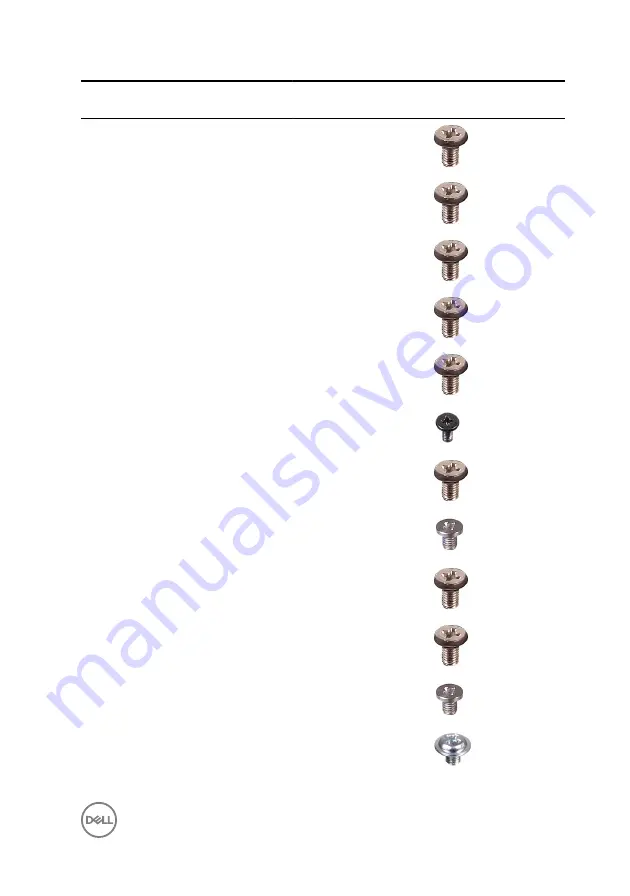
Component
Secured to
Screw
type
Quantity
Screw image
I/O panel
Middle frame
M3x5
9
I/O board
Middle frame
M3x5
4
I/O bracket
Middle frame
M3x5
9
Inner frame
Middle frame
M3x5
9
Media-card
reader
Middle frame
M3x5
2
Microphones (4) Middle frame
M2x4
4
Middle frame
Display panel
M3x5
11
Power-button
board
Middle frame
M2x3.5
2
Side I/O-board
Middle frame
M3x5
2
Side I/O-board
bracket
Middle frame
M3x5
2
Solid-state drive System board
M2x3.5
1
Speakers (2)
Middle frame
Washer-
type
M3x4
4
13
Summary of Contents for Inspiron 24 5000 Series
Page 21: ...2 Slide and lift the back cover off the inner frame 21 ...
Page 32: ...2 Gently pry the inner frame from the sides off the middle frame 32 ...
Page 33: ...3 Lift the inner frame from the middle frame 33 ...
Page 36: ...3 Disconnect the camera cable WEBCAM from the camera assembly 36 ...
Page 44: ...3 Replace the back cover 44 ...
Page 50: ...2 Lift the system board shield off the middle frame 50 ...
Page 53: ...3 Lift the chassis fan off the middle frame 53 ...
Page 56: ...5 Lift the speakers along with the cable off the middle frame 56 ...
Page 58: ...4 Replace the back cover 58 ...
Page 61: ...8 Lift the media card reader board from the side I O bracket 61 ...
Page 69: ...3 Slide and remove the memory module from the memory module slot 69 ...
Page 78: ...5 Slide and remove the wireless card out of the wireless card slot 78 ...
Page 87: ...4 Gently lift the processor and remove it from the processor socket 87 ...
Page 91: ...2 Lift the I O bracket off the middle frame 91 ...
Page 95: ...11 Lift the I O board off the middle frame 95 ...
Page 101: ...19 Lift the system board off the middle frame 101 ...
Page 115: ...9 Disconnect the touch screen cable TOUCH1 from the display panel 115 ...