


Processor Module (For Inspiron 14-N4050 Only)
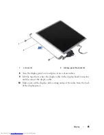
51
14
Processor Module (For Inspiron
14-N4050 Only)
WARNING:
Before working inside your computer, read the safety information
that shipped with your computer. For additional safety best practices information,
see the Regulatory Compliance Homepage at
www.dell.com/regulatory_compliance.
CAUTION:
Only a certified service technician should perform repairs on your
computer. Damage due to servicing that is not authorized by Dell is not covered by
your warranty.
CAUTION:
To avoid electrostatic discharge, ground yourself by using a wrist
grounding strap or by periodically touching an unpainted metal surface (such as a
connector on your computer).
CAUTION:
To help prevent damage to the system board, remove the main battery
(see "Removing the Battery" on page 13) before working inside the computer.
CAUTION:
Handle components and cards by their edges, and avoid touching pins
and contacts.
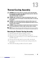
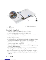
Removing the Processor Module
1
Follow the instructions in "Before You Begin" on page 9.
2
Remove the battery (see "Removing the Battery" on page 13).
3
Follow the instructions from step 3 to step 8 in "Removing the Palm-Rest
Assembly" on page 25.
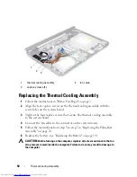
4
Remove the thermal cooling assembly (see "Removing the Thermal
Cooling Assembly" on page 49).
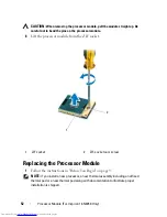
5
To loosen the ZIF socket, use a small, flat-blade screwdriver and rotate the
ZIF-socket cam screw counterclockwise until it comes to stop.
CAUTION:
To ensure maximum cooling for the processor, do not touch the heat
transfer areas on the processor thermal cooling assembly. The oils in your skin
can reduce the heat transfer capability of the thermal pads.
Summary of Contents for Inspiron 3420
Page 7: ...Contents 7 ...
Page 8: ...8 Contents ...
Page 12: ...12 Before You Begin ...
Page 18: ...18 Keyboard ...
Page 22: ...22 Memory ...
Page 30: ...30 Palm Rest Assembly ...
Page 36: ...36 Hard Drive ...
Page 40: ...40 Wireless Mini Card ...
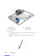
Page 46: ...46 Coin Cell Battery ...
Page 54: ...54 Processor Module For Inspiron 14 N4050 Only ...
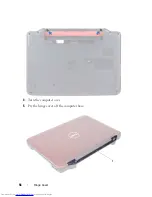
Page 56: ...56 Hinge Cover 4 Turn the computer over 5 Pry the hinge cover off the computer base 1 ...
Page 58: ...58 Hinge Cover ...
Page 68: ...68 Display ...
Page 72: ...72 Camera Module ...


