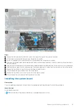


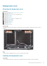


8. Remove the
.
9. Remove the
.
10. Remove the
11. Remove the
.
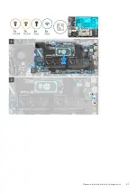
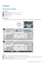
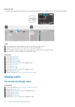
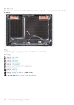
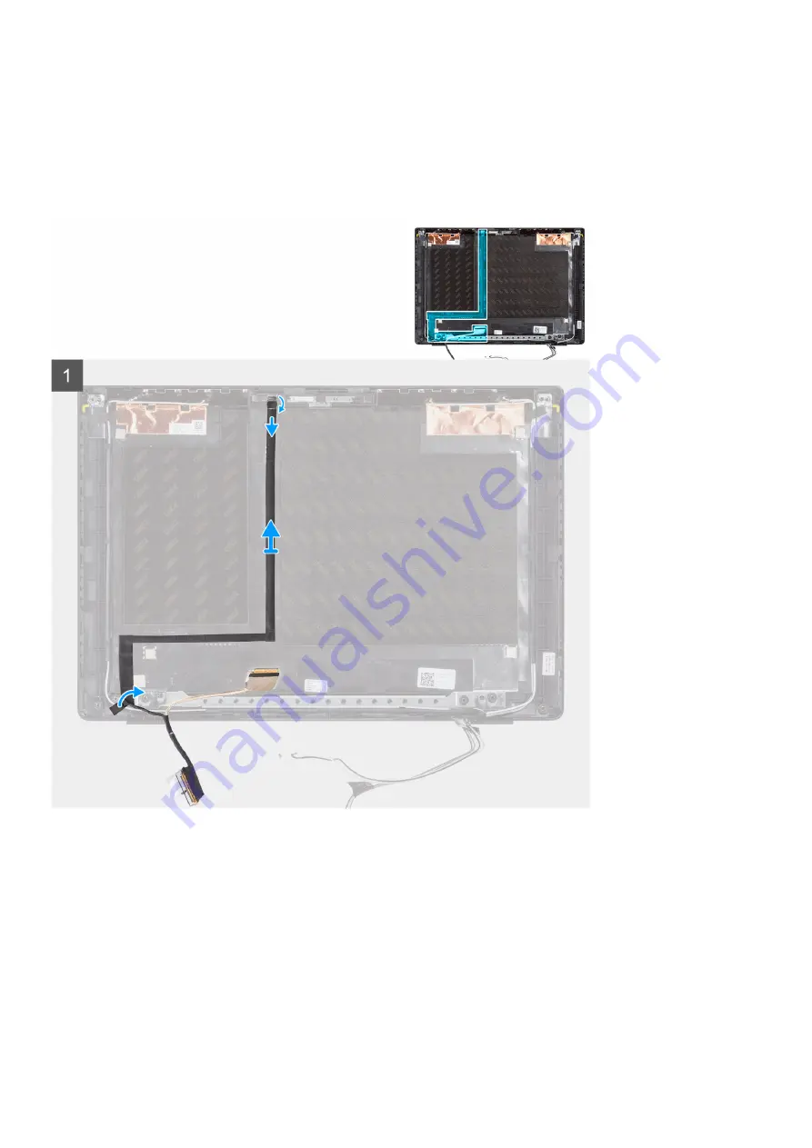
About this task
The following image indicates the location of the display cable and provides a visual representation of the removal procedure.
Steps
1. Disconnect the display cable from the connector on the system board.
2. Disconnect the display cable from the connector on the display panel.
3. Disconnect the display cable from the connector on the camera module.
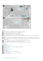
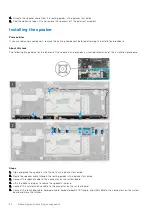
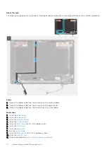
Installing the display cable
Prerequisites
If you are replacing a component, remove the existing component before performing the installation procedure.
Removing and installing components
93
Summary of Contents for Inspiron 3420
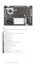
Page 13: ...Major components of your system 1 Base cover Removing and installing components 13 ...
Page 55: ...Removing and installing components 55 ...
Page 56: ...56 Removing and installing components ...
Page 58: ...58 Removing and installing components ...
Page 78: ...78 Removing and installing components ...


