


3
Press F12 after the Dell logo is displayed on the screen to access the boot menu.
A
Preparing one-time boot menu
message appears.
4
After the boot menu loads, select the USB recovery device under
UEFI BOOT
.
The system reboots and a screen to
Choose the keyboard layout
is displayed.
5
Choose your keyboard layout.
6
In the
Choose an option
screen, click
Troubleshoot
.
7
Click
Recover from a drive
.
8
Choose one of the following options:
–
Just remove my files
to do a quick format.
–
Fully clean the drive
to do a complete format.
9
Click
Recover
to start the recovery process.
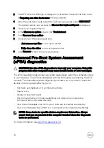
Enhanced Pre-Boot System Assessment
(ePSA) diagnostics
CAUTION: Use the ePSA diagnostics to test only your computer. Using this
program with other computers may cause invalid results or error messages.
The ePSA diagnostics (also known as system diagnostics) performs a complete check
of your hardware. The ePSA is embedded with the BIOS and is launched by the BIOS
internally. The embedded system diagnostics provides a set of options for particular
devices or device groups allowing you to:
•
Run tests automatically or in an interactive mode
•
Repeat tests
•
Display or save test results
•
Run thorough tests to introduce additional test options to provide extra
information about the failed device(s)
•
View status messages that inform you if tests are completed successfully
•
View error messages that inform you of problems encountered during testing
NOTE: Some tests for specific devices require user interaction. Always
ensure that you are present at the computer terminal when the diagnostic
tests are performed.
For more information, see
.
78
Summary of Contents for Inspiron 3472
Page 14: ...System board components 1 power button cable connector 2 coin cell battery 14 ...
Page 28: ...2 Remove the two screws 6 32xL6 35 that secure the hard drive assembly to the drive cage 28 ...
Page 30: ...5 Slide the hard drive out of the hard drive bracket 30 ...
Page 41: ...2 Remove the coin cell battery from the socket 41 ...
Page 45: ...5 Slide and remove the wireless card from the wireless card slot 45 ...
Page 49: ...3 Remove the antenna modules along with the cables off the chassis 49 ...
Page 53: ...5 Remove the power button module along with its cable through the slot on the front panel 53 ...
Page 56: ...3 Lift the thermal cooling assembly off the system board 56 ...
Page 61: ...8 Slide and lift the system board off the chassis 61 ...


